 ChipApex | Global Electronic Components Supplier

SEARCH
Search Product
Search Post
— IC芯片 | 连接器 | 传感器 | 被动器件 —
Search productSearch post
— IC芯片 | 连接器 | 传感器 | 被动器件 —
Consult the customer manager about the wholesale price.
consultation hotline:86-132-6715-2157
email:[email protected]
Contact the product manager for consultation. One-stop consultation is available.
Do you want a lower wholesale price? Please send us your inquiry and we will reply immediately.
The ISP827 is a high-density mounting phototransistor optically coupled isolator manufactured by Isocom Components. It features a dual-element configuration housed in a plastic DIP-8 package, providing 5300 V isolation voltage between input and output circuits. The device operates within a temperature range of -55 °C to +100 °C and supports a maximum forward current of 0.05 A. Key electrical parameters include a minimum collector-emitter breakdown voltage of 35 V, a nominal current transfer ratio of 200%, and a maximum dark power of 100 nA. The component is UL recognized (File No. E91231) and VDE approved under standard 0884.
Verify the specific lead form suffix (STD or G) required for your PCB layout, as these physical variations affect pin spacing and mounting compatibility. Confirm that the application environment stays within the specified -55 °C to +100 °C operating temperature range to ensure reliable performance. Check for compliance with RoHS directives if environmental regulations apply to your manufacturing process.
Select this component when dual-channel isolation is necessary within a compact DIP-8 footprint. The 200% nominal current transfer ratio makes it suitable for applications demanding efficient signal coupling. Ensure the design accommodates the 5300 V isolation rating to meet safety clearance requirements. Consider the thermal limits if the device will operate near the upper boundary of its specified temperature range.
The ISP827 belongs to the ISP817/ISP827/ISP847 series of high-density mounting phototransistor optically coupled isolators from Isocom Components. This family offers various channel counts and packaging options to suit different isolation needs. The 'X' designation in related datasheets indicates specific approval specifications, while the base model defines the core electrical characteristics and channel configuration.
Compatible substitutes within the same manufacturer series include the ISP817 for single-channel applications and the ISP847 for four-channel configurations. When replacing, verify that the alternative part matches the required isolation voltage and current transfer ratio. Ensure the physical package dimensions and lead form are compatible with the existing board layout.
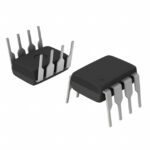 ISP827

The activity of extra discounts on wholesale prices is in full swing…
Please fill in your contact information and we will send you the latest wholesale price list.






