ChipApex | Global Electronic Components Supplier

SEARCH
Search Product
Search Post
— IC芯片 | 连接器 | 传感器 | 被动器件 —
Search productSearch post
— IC芯片 | 连接器 | 传感器 | 被动器件 —
Consult the customer manager about the wholesale price.
consultation hotline:86-132-6715-2157
email:[email protected]
Contact the product manager for consultation. One-stop consultation is available.
Do you want a lower wholesale price? Please send us your inquiry and we will reply immediately.
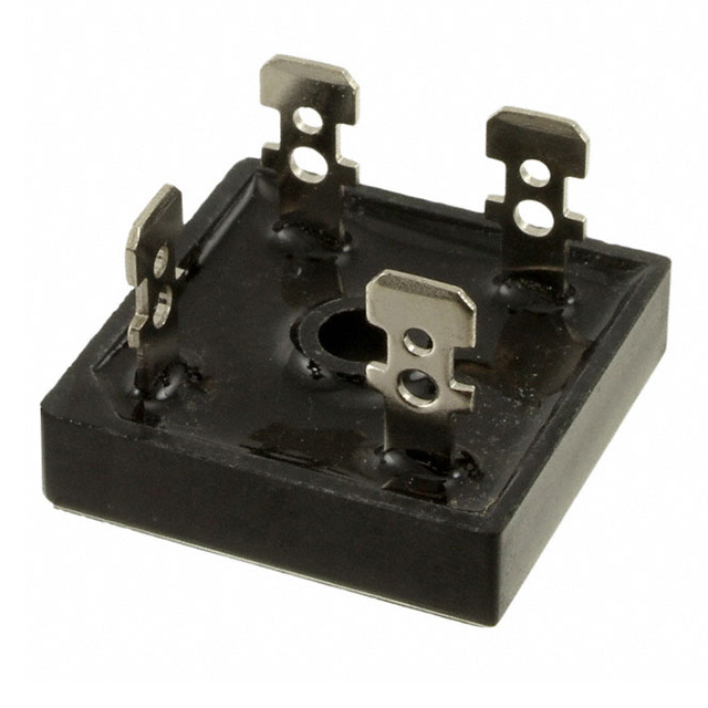
The GeneSiC Semiconductor KBPC5008T is a single-phase silicon bridge rectifier designed for high-efficiency power conversion. It features a maximum average forward rectified current (IO) of 50 A and a repetitive peak reverse voltage (VRRM) of 800 V. The device supports a DC blocking voltage (VDC) of 800 V and an RMS reverse voltage (VRMS) of 560 V. It withstands a peak forward surge current (IFSM) of 400 A under standard conditions. The typical thermal resistance per leg (RΘJC) is 2.5 °C/W. The component operates within a junction temperature range of -55 °C to +150 °C.
Verify the specific datasheet version and manufacturer documentation before procurement, as GeneSiC Semiconductor has undergone corporate restructuring and brand transitions. Confirm that the supplier provides original manufacturer packaging and traceability documents. Ensure the component matches the KBPC-T package specification and check for any potential obsolescence notices or lifecycle status updates from the current authorized distributor network.
Select this component when a 50 A continuous current rating and 800 V reverse voltage capability are required. The KBPC-T package offers robust mechanical mounting via screw holes, suitable for applications requiring secure attachment to heat sinks. Consider the 2.5 °C/W thermal resistance for heatsink design calculations. Derate the forward current by 20% if the load is capacitive rather than resistive or inductive.
The KBPC5008T belongs to the KBPC5006T/W through KBPC5010T/W series of single-phase bridge rectifiers. This family shares identical physical dimensions and thermal characteristics, differing primarily in their voltage ratings. The 'T' suffix indicates the use of the KBPC-T package style. These components are engineered for general-purpose rectification tasks where high current handling and reliable thermal performance are critical requirements.
Direct replacements must match the 50 A current rating, 800 V voltage rating, and KBPC-T package footprint. Verify that substitute parts maintain the same 2.5 °C/W thermal resistance and operating temperature range. Cross-reference pinouts to ensure polarity markings align correctly with the existing circuit board layout.
 KBPC5008T

The activity of extra discounts on wholesale prices is in full swing…
Please fill in your contact information and we will send you the latest wholesale price list.