 ChipApex | Global Electronic Components Supplier

SEARCH
Search Product
Search Post
— IC芯片 | 连接器 | 传感器 | 被动器件 —
Search productSearch post
— IC芯片 | 连接器 | 传感器 | 被动器件 —
Consult the customer manager about the wholesale price.
consultation hotline:86-132-6715-2157
email:[email protected]
Contact the product manager for consultation. One-stop consultation is available.
Do you want a lower wholesale price? Please send us your inquiry and we will reply immediately.
The L79L06ACZ is a three-terminal negative voltage regulator from the L79L series by STMicroelectronics, housed in a TO-92 package. It provides a fixed output voltage of -6 V with an accuracy of ±5%. The device supports an output current up to 100 mA and operates within a junction temperature range of 0°C to +125°C. Key electrical characteristics include a maximum dropout voltage of 1.7 V, a typical quiescent current of 6 mA, and supply voltage rejection of 46 dB at 120 Hz. Input voltage limits are specified between -8.5 V and -20 V for line regulation testing.
Verify the specific suffix 'Z' corresponds to the TO-92 tube packaging configuration when sourcing. Confirm that the AC designation ensures the required ±5% output voltage tolerance for the application. Ensure input voltage constraints remain within the absolute maximum ratings to prevent device damage during procurement validation.
Select this component for low-current negative rail requirements where simplicity and cost-effectiveness are priorities. The TO-92 package suits through-hole designs with moderate thermal dissipation needs. Consider the 1.7 V dropout voltage when determining the minimum required input voltage headroom relative to the load current and operating temperature range.
This part belongs to the L79L00 series of three-terminal negative regulators. The series includes variants with different fixed output voltages such as -5 V, -8 V, -9 V, -12 V, and -15 V. The 'AC' suffix indicates a tighter ±5% output voltage tolerance compared to the standard 'C' variant, which offers ±10% accuracy.
Direct functional substitutes within the same series include L79L05ACZ (-5 V) and L79L08ACZ (-8 V). For pin-compatible alternatives with different tolerances, consider L79L06CZ (±10%) or L79L06ABZ (-40°C to 125°C operating range).
The device can deliver up to 100 mA of output current, provided adequate heat sinking is utilized to manage power dissipation.
No external components are strictly required for basic operation, though the datasheet test circuits typically include input and output capacitors (e.g., 0.33 µF and 0.1 µF) for optimal performance.
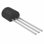 L79L06ACZ

The activity of extra discounts on wholesale prices is in full swing…
Please fill in your contact information and we will send you the latest wholesale price list.




