 ChipApex | Global Electronic Components Supplier

SEARCH
Search Product
Search Post
— IC芯片 | 连接器 | 传感器 | 被动器件 —
Search productSearch post
— IC芯片 | 连接器 | 传感器 | 被动器件 —
Consult the customer manager about the wholesale price.
consultation hotline:86-132-6715-2157
email:[email protected]
Contact the product manager for consultation. One-stop consultation is available.
Do you want a lower wholesale price? Please send us your inquiry and we will reply immediately.
LMK1D2102RGTT is listed in the Clock Buffers, Drivers range at ChipApex. The manufacturer field lists Texas Instruments. Its product description is IC CLK BUFFER 1:2 2GHZ 16VQFN. Review the specifications below when checking this part for your BOM.
The LMK1D2102RGTT is a low additive jitter LVDS clock buffer manufactured by Texas Instruments. It features dual 1:2 differential buffering, distributing two inputs (IN0, IN1) to four LVDS outputs (OUT0–OUT3). The device supports input frequencies up to 2 GHz and operates on a supply voltage of 1.71 V to 3.465 V. Key electrical parameters include a maximum propagation delay of 575 ps, output skew of 20 ps, and random additive jitter below 60 fs RMS at 156.25 MHz. It accepts universal input levels including LVDS, LVPECL, HCSL, CML, and LVCMOS. The component is housed in a 3 mm × 3 mm 16-pin VQFN package.
Verify the ordering suffix 'RGT' corresponds to the 16-pin VQFN package configuration. Confirm that the specific revision level matches the design requirements, as datasheets are subject to updates. Ensure the procurement source provides valid traceability for this Texas Instruments component.
Select the LMK1D2102RGTT when a dual-bank buffer with only two outputs per bank is required, offering a smaller footprint than the 8-output LMK1D2104. Verify that the system requires exactly four LVDS outputs total. Check that the input signal levels match the supported universal inputs and that the 50 Ω transmission line driving capability meets the PCB layout constraints.
This component belongs to the LMK1D210x family of ultra-low additive jitter LVDS buffers. The family includes variants such as the LMK1D2104 (dual 1:4), LMK1D2106M (dual 1:6), and LMK1D2108M (dual 1:8). All members share similar electrical characteristics regarding jitter and input compatibility but differ in output count and package size.
LMK1D2104RGTR: Offers eight outputs instead of four in the same package; verify pin compatibility if unused pins are left floating or terminated.
When the EN pin is open, all outputs are enabled. A logic '0' disables both banks. A logic '1' enables one bank while disabling the other.
Yes, unused inputs can be left floating due to the device's fail-safe input operation and input hysteresis, which prevents random oscillation.
TI recommends terminating unused outputs differentially with a 100 Ω resistor for optimum performance, although unterminated outputs are also acceptable.
Explore related parts through Clock/Timing, Integrated Circuits (ICs), all product categories, ChipApex homepage.
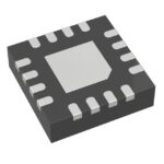 LMK1D2102RGTT

The activity of extra discounts on wholesale prices is in full swing…
Please fill in your contact information and we will send you the latest wholesale price list.





