 ChipApex | Global Electronic Components Supplier
SEARCH
Search Product
Search Post
— IC芯片 | 连接器 | 传感器 | 被动器件 —
Search productSearch post
— IC芯片 | 连接器 | 传感器 | 被动器件 —
Consult the customer manager about the wholesale price.
consultation hotline:86-132-6715-2157
email:[email protected]
Contact the product manager for consultation. One-stop consultation is available.
Do you want a lower wholesale price? Please send us your inquiry and we will reply immediately.
The LT1944-1EMS#PBF is a dual micropower step-up DC/DC converter housed in a 10-pin MSOP package. It integrates two independent boost converters with distinct current limits: one channel provides a 100mA switch current limit, while the second offers a higher capacity. The device operates from an input voltage range of 1.2V to 15V and supports adjustable output voltages up to 34V. Designed for low quiescent current applications, it enables efficient power management in battery-operated systems requiring multiple regulated rails.
Verify the specific suffix #PBF indicates lead-free RoHS compliance when ordering. Confirm the MSOP-10 package dimensions match your PCB footprint requirements. Ensure the input voltage range aligns with your source battery characteristics. Check for availability constraints as this component may have limited stock status. Validate that the 100mA and secondary channel current limits meet your load requirements.
Select this component when dual isolated or non-isolated boost outputs are required from a low-voltage source. Compare against standard single-channel converters if only one rail is needed to save space. Consider the 100mA limit of the primary channel for load sizing. Evaluate the quiescent current specifications against system sleep mode requirements. Ensure the 34V maximum output capability exceeds your target voltage needs.
This part belongs to Analog Devices' LT1944 family of micropower switching regulators. The LT1944 variant features two 350mA channels, whereas the LT1944-1 distinguishes itself with a 100mA primary channel and a secondary channel rated at 175mA. This differentiation allows designers to optimize cost and performance for asymmetric load distributions in compact mobile electronics.
LT1944EMS#PBF serves as a functional alternative with symmetric 350mA channels. Verify pin compatibility and thermal performance when substituting. Ensure the replacement meets the same input voltage and output voltage ranges. Confirm package integrity remains consistent for existing PCB layouts.
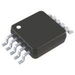 LT1944-1EMS#PBF
The activity of extra discounts on wholesale prices is in full swing…
Please fill in your contact information and we will send you the latest wholesale price list.





