 ChipApex | Global Electronic Components Supplier
SEARCH
Search Product
Search Post
— IC芯片 | 连接器 | 传感器 | 被动器件 —
Search productSearch post
— IC芯片 | 连接器 | 传感器 | 被动器件 —
Consult the customer manager about the wholesale price.
consultation hotline:86-132-6715-2157
email:[email protected]
Contact the product manager for consultation. One-stop consultation is available.
Do you want a lower wholesale price? Please send us your inquiry and we will reply immediately.
The LTC1064CSW#TRPBF is a low noise, fast, quad universal filter building block manufactured by Analog Devices Inc. It consists of four high-speed switched-capacitor filter sections housed in a 24-lead plastic SO Wide package. The device supports a maximum center frequency of 140 kHz and operates with power supplies ranging from ±2.375 V to ±8 V. It features a maximum clock frequency of 7 MHz and provides clock-to-center frequency ratios of 50:1 and 100:1 simultaneously available. The component offers low offsets, low harmonic distortion, and wide frequency range tracking capabilities.
Verify the specific ordering suffix #TRPBF confirms tape and reel packaging and lead-free compliance when sourcing this component. Confirm that the CSW designation corresponds to the 24-lead SO Wide package variant required for your printed circuit board layout constraints. Ensure compatibility with the intended operating temperature range specifications before finalizing procurement orders.
Select this component when designing circuits requiring multiple synchronized filter sections within a single integrated circuit. Consider the maximum clock frequency limits relative to the desired center frequencies and Q factors. Evaluate the supply voltage requirements against the ±2.375 V to ±8 V operational range to ensure adequate headroom for signal swings and internal op amp performance.
This part belongs to the LTC1064 series of active filters. It serves as a versatile building block for constructing higher-order filters by cascading its internal sections. The device is designed for applications demanding precise frequency control and low noise characteristics in analog signal conditioning paths.
Consult manufacturer documentation for customized monolithic versions with internal thin film resistors if high volume production requires fixed resistor values. Verify pinout and electrical specifications against other switched-capacitor filter families before substitution.
By tying Pin 17 to V+, all sections operate with a 50:1 ratio. By tying Pin 17 to V–, all sections operate with a 100:1 ratio. Connecting Pin 17 to AGND allows Sections B and C to operate at 50:1 while Sections A and D operate at 100:1.
The maximum clock frequency is 7 MHz for supply voltages of ±7 V and above. For ±5 V supplies, the maximum clock frequency is limited to 4 MHz.
Yes, the device can operate with a single positive supply. In this configuration, the Analog Ground (AGND) pin should be tied to half the supply voltage and properly bypassed.
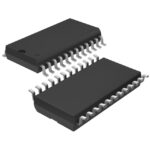 LTC1064CSW#TRPBF
The activity of extra discounts on wholesale prices is in full swing…
Please fill in your contact information and we will send you the latest wholesale price list.





