 ChipApex | Global Electronic Components Supplier

SEARCH
Search Product
Search Post
— IC芯片 | 连接器 | 传感器 | 被动器件 —
Search productSearch post
— IC芯片 | 连接器 | 传感器 | 被动器件 —
Consult the customer manager about the wholesale price.
consultation hotline:86-132-6715-2157
email:[email protected]
Contact the product manager for consultation. One-stop consultation is available.
Do you want a lower wholesale price? Please send us your inquiry and we will reply immediately.
LTC1099CN#30369 is listed in the Analog To Digital Converters (ADC) range at ChipApex. The manufacturer field lists Analog Devices Inc.. Its product description is IC ADC 8BIT FLASH 20DIP. Review the specifications below when checking this part for your BOM.
The LTC1099CN is an 8-bit analog-to-digital converter featuring a built-in sample-and-hold circuit. It operates on a single 5V supply and supports parallel data output with three-state control. The device offers two operational modes: Read (RD) mode for processor interfaces and Write-Read (WR-RD) mode for standalone applications. Key electrical specifications include a typical conversion time of 2.5µs, a maximum power dissipation of 75mW, and a total unadjusted error of -1 LSB. The component is housed in a 20-lead PDIP package and functions within an ambient temperature range of 0°C to 70°C.
Verify the specific suffix against official documentation to confirm package type and temperature grade. The CN designation indicates a plastic DIP package with commercial operating limits. Confirm RoHS compliance status through current manufacturer declarations as regulatory statuses may change over time.
Select this component when an 8-bit resolution with integrated sampling is required for 5V logic systems. Ensure the input signal slew rate does not exceed 2.5V/ms to maintain accuracy without external conditioning. Consider the WR-RD mode if processor timing flexibility is needed, or RD mode for standard ready-strobe interfacing.
This part belongs to the LTC1099 family of high-speed ADCs. Variants such as the AC and AI grades offer improved linearity specifications (-0.75 LSB vs -1 LSB). The family utilizes a 2-step flash architecture to reduce comparator count while maintaining speed. Other members include different package options like the SW (SOIC) variant.
Direct replacements must match the 8-bit resolution, parallel interface, and 20-pin PDIP footprint. Verify that substitute devices support the same 5V single-supply operation and provide comparable conversion times. Check for compatible timing characteristics in both RD and WR-RD modes.
Explore related parts through Data Acquisition, Integrated Circuits (ICs), all product categories, ChipApex homepage.
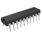 LTC1099CN#30369

The activity of extra discounts on wholesale prices is in full swing…
Please fill in your contact information and we will send you the latest wholesale price list.




