 ChipApex | Global Electronic Components Supplier

SEARCH
Search Product
Search Post
— IC芯片 | 连接器 | 传感器 | 被动器件 —
Search productSearch post
— IC芯片 | 连接器 | 传感器 | 被动器件 —
Consult the customer manager about the wholesale price.
consultation hotline:86-132-6715-2157
email:[email protected]
Contact the product manager for consultation. One-stop consultation is available.
Do you want a lower wholesale price? Please send us your inquiry and we will reply immediately.
LTC1406IGN#PBF is listed in the Analog To Digital Converters (ADC) range at ChipApex. The manufacturer field lists Analog Devices Inc.. Its product description is IC ADC 8BIT PIPELINED 24SSOP. Review the specifications below when checking this part for your BOM.
The LTC1406IGN#PBF is an 8-bit, 20Msps sampling A/D converter in a 24-lead narrow SSOP package. It features a 250MHz internal sample-and-hold and accepts ±1V differential or 2V single-ended inputs. Powered by a single 5V supply, it dissipates 150mW at full throughput and draws 1μA in shutdown mode. The device provides true differential inputs with 60dB common-mode rejection and includes overflow/underflow detection. Digital outputs interface with 3V or 5V logic via separate OVDD/OGND supplies.
Verify the suffix IGN#PBF corresponds to the industrial temperature range (-40°C to +85°C) and lead-free RoHS compliance. Confirm the package is the 24-lead narrow SSOP. Ensure the source document matches the Analog Devices datasheet for the LTC1406 family.
Select this component for applications requiring low power consumption and wide dynamic range at moderate resolution. The 250MHz bandwidth supports undersampling techniques. Ensure the driving circuit can settle within 25ns to maintain performance at 20Msps. Use an external 2.5V reference on the VREF pin for optimal linearity.
This part belongs to the LTC1406 series of low-power, high-speed ADCs from Analog Devices. It utilizes a pipelined architecture with five clock cycles of latency. The device is designed for easy integration into systems requiring 8-bit precision at 20Msps with minimal external components.
Public confirmed substitute part numbers are not available in the provided documentation.
The OF/UF pin indicates these states. A logic high with all data outputs low indicates underrange; a logic high with all data outputs high indicates overrange.
The minimum conversion rate is 10kHz. Below this frequency, internal circuitry may not operate correctly due to dynamic limitations.
Yes, by connecting the OVDD pin to a 3V supply instead of the standard 5V DVDD, the digital outputs will be compatible with 3V logic levels.
Explore related parts through Data Acquisition, Integrated Circuits (ICs), all product categories, ChipApex homepage.
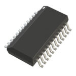 LTC1406IGN#PBF

The activity of extra discounts on wholesale prices is in full swing…
Please fill in your contact information and we will send you the latest wholesale price list.




