ChipApex | Global Electronic Components Supplier

SEARCH
Search Product
Search Post
— IC芯片 | 连接器 | 传感器 | 被动器件 —
Search productSearch post
— IC芯片 | 连接器 | 传感器 | 被动器件 —
Consult the customer manager about the wholesale price.
consultation hotline:86-132-6715-2157
email:[email protected]
Contact the product manager for consultation. One-stop consultation is available.
Do you want a lower wholesale price? Please send us your inquiry and we will reply immediately.
LTC2053IMS8#PBF is listed in the Instrumentation, Op Amps, Buffer Amps range at ChipApex. The manufacturer field lists Analog Devices Inc.. Its product description is IC OPAMP ZERO-DRIFT 1 CIRC 8MSOP. Review the specifications below when checking this part for your BOM.
The LTC2053IMS8#PBF is a precision, rail-to-rail, zero-drift instrumentation amplifier in an 8-lead MSOP package. It operates on single supplies from 2.7V to 5.5V or dual supplies up to ±5.5V. Key electrical characteristics include a typical CMRR of 116dB independent of gain, maximum input offset voltage of 10µV, and average drift below 50nV/°C over the industrial temperature range. Gain is programmable via two external resistors with a formula of 1 + R2/R1. The device draws a typical supply current of 750µA and features a shutdown mode consuming 10µA.
Verify the specific suffix #PBF indicates lead-free and RoHS compliance status as per manufacturer documentation. Confirm the IMS8 designation corresponds to the 8-lead plastic MSOP package variant. Ensure the 'I' grade matches the required -40°C to 85°C operating temperature range for the target application environment.
Select this component when ultra-low offset voltage and drift are critical requirements. The standard LTC2053 version lacks an external clock pin; use the SYNC variant if synchronization to an external system clock is necessary to prevent aliasing. Consider source resistance limitations, as mismatches greater than 10k may introduce DC errors due to internal sampling currents.
This part belongs to the LTC2053 family of zero-drift instrumentation amplifiers. It shares architectural similarities with the LTC2053-SYNC but differs by integrating an internal oscillator rather than requiring an external clock signal on Pin 1. The IMS8 package provides a compact surface-mount solution suitable for space-constrained designs compared to larger DFN options.
LTC2053IMS8#TRPBF (Tape and Reel)
The gain is set by two external resistors connected between the RG pin and the inverting input, following the formula Gain = 1 + R2/R1.
Pin 1 serves as the active-low Enable (EN) pin to control the device's power state, allowing for a shutdown current of 10µA.
Explore related parts through Amplifiers, Linear, Integrated Circuits (ICs), all product categories.
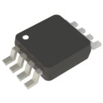 LTC2053IMS8#PBF

The activity of extra discounts on wholesale prices is in full swing…
Please fill in your contact information and we will send you the latest wholesale price list.