 ChipApex | Global Electronic Components Supplier

SEARCH
Search Product
Search Post
— IC芯片 | 连接器 | 传感器 | 被动器件 —
Search productSearch post
— IC芯片 | 连接器 | 传感器 | 被动器件 —
Consult the customer manager about the wholesale price.
consultation hotline:86-132-6715-2157
email:[email protected]
Contact the product manager for consultation. One-stop consultation is available.
Do you want a lower wholesale price? Please send us your inquiry and we will reply immediately.
MADP-030015-13140G is listed in the RF Diode range at ChipApex. The manufacturer field lists MACOM Technology Solutions. Its product description is RF DIODE PIN 115V. Review the specifications below when checking this part for your BOM.
The MADP-030015-1314G is a silicon PIN diode surmount chip from the MAPD-0xx015 series, utilizing MACOM's HMIC process. It features a 15 µm I-region length and an ODS-1314 case style with a 0603 outline. The device operates within a temperature range of -55°C to +125°C. Key electrical specifications include a maximum reverse voltage of 115 V, a typical capacitance of 0.78 pF at 1 GHz (-40 V bias), and a typical series resistance of 0.49 Ω at 1 GHz (+70 mA forward current). It supports a maximum forward current of 500 mA and offers high power handling capabilities.
Verify the specific ordering suffix when sourcing this component. The 'G' suffix denotes a 100-piece gel pack configuration, which differs from the 'P' suffix used for 3000-piece reels. Confirm packaging requirements with the manufacturer or authorized distributor to ensure the correct quantity format is received for prototyping or production needs.
Select the MADP-030015 variant over the MADP-017015 when higher capacitance is acceptable or required for specific circuit impedance matching. This model provides a lower thermal resistance of 13 °C/W compared to 30 °C/W in the 017015 version, making it suitable for applications where efficient heat dissipation is critical despite the slightly higher capacitive load.
This component belongs to the MAPD-0xx015 SURMOUNT family, characterized by 15 µm I-region lengths and HMIC fabrication technology. These devices are designed as bare chips rather than traditional packaged diodes, allowing for direct surface mounting on substrates. The ODS-1314 case style defines the physical dimensions and contact pad layout for these specific surmount chips.
The MADP-017015-1314G is a related part within the same datasheet but exhibits different electrical characteristics, specifically lower capacitance and higher thermal resistance. Direct substitution requires verifying that the circuit design can accommodate the change in capacitance from approximately 0.32 pF to 0.78 pF and the difference in thermal management requirements.
The thermal resistance (θ) is typically 13 °C/W, measured with the die mounted in an ODS-186 package.
Attachment is achieved through surface mount technology using solder attachment onto hard or soft substrates. Recommended solders include 80Au/20Sn or RoHS compliant variants, with conductive silver epoxy also usable for average power applications around 1 W.
The maximum operating temperature is +125°C, while the storage temperature range extends up to +150°C.
Explore related parts through Diodes, Discrete Semiconductor Products, all product categories, ChipApex homepage.
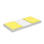 MADP-030015-13140G

The activity of extra discounts on wholesale prices is in full swing…
Please fill in your contact information and we will send you the latest wholesale price list.




