 ChipApex | Global Electronic Components Supplier

SEARCH
Search Product
Search Post
— IC芯片 | 连接器 | 传感器 | 被动器件 —
Search productSearch post
— IC芯片 | 连接器 | 传感器 | 被动器件 —
Consult the customer manager about the wholesale price.
consultation hotline:86-132-6715-2157
email:[email protected]
Contact the product manager for consultation. One-stop consultation is available.
Do you want a lower wholesale price? Please send us your inquiry and we will reply immediately.
MAX213ECWI+T is listed in the Drivers, Receivers, Transceivers range at ChipApex. The manufacturer field lists Analog Devices Inc./Maxim Integrated. Its product description is IC TRANSCEIVER FULL 4/5 28SOIC. Review the specifications below when checking this part for your BOM.
The MAX213ECWI+T is a single-supply RS-232 transceiver from the MAX202E–MAX213E family, manufactured by Analog Devices Inc./Maxim Integrated. It operates on a single +5V supply (4.5V to 5.5V) and integrates dual charge-pump voltage converters to generate ±10V internal rails without requiring external bipolar supplies. The device features four drivers and five receivers with two awake-in-shutdown receiver outputs. It supports data rates up to 120kbps and provides ±15kV ESD protection via the Human Body Model. The EC suffix indicates an industrial temperature range of 0°C to +70°C, and the W package denotes a 28-pin SSOP form factor.
Verify the specific ordering suffix against official documentation to confirm the package type and temperature grade. The 'W' suffix corresponds to the 28-pin SSOP package, and 'C' indicates the commercial/industrial temperature range. Ensure that the required capacitor values match the datasheet specifications for the charge pump capacitors to guarantee proper voltage generation.
Select this component when a single +5V supply is available and high ESD protection is required for harsh environments. The MAX213E is distinct within the family due to its enable and shutdown control pins and the inclusion of two receivers that function independently of the shutdown state. Verify that the 120kbps data rate meets the application requirements before choosing over higher-speed alternatives.
This part belongs to the MAX202E–MAX213E family of RS-232 transceivers designed for rugged applications. The 'E' designation signifies enhanced ESD protection compared to standard versions. The MAX213E variant specifically adds control functionality for power management through dedicated Enable and Shutdown pins, differentiating it from non-controlled counterparts like the MAX211E.
The MAX211EEWI+ is a parameter-equivalent alternative within the same family but lacks the awake-in-shutdown receiver capability and has different control pin polarities. Direct substitution requires verifying the logic levels for the Enable and Shutdown pins, as they are inverted between the MAX211E and MAX213E variants.
In shutdown mode, the MAX213E disables the charge pumps and most driver/receiver outputs to save power. However, receivers R4 and R5 remain active to monitor external signals, allowing the system to detect wake-up events without consuming full operating current.
For the MAX213E, the Enable (EN) pin is active high, and the Shutdown (SHDN) pin is active low. This is opposite to the MAX211E and MAX241E, where EN is active low and SHDN is active high.
The MAX213E requires four external 0.1μF capacitors connected to the charge pump terminals (C1+, C1-, C2+, C2-). Ceramic dielectrics are recommended for these capacitors.
Explore related parts through Interface, Integrated Circuits (ICs), all product categories, ChipApex homepage.
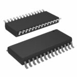 MAX213ECWI+T

The activity of extra discounts on wholesale prices is in full swing…
Please fill in your contact information and we will send you the latest wholesale price list.






