 ChipApex | Global Electronic Components Supplier
MAX25615AUT/V+T
Search Product
Search Post
— IC芯片 | 连接器 | 传感器 | 被动器件 —
Search productSearch post
— IC芯片 | 连接器 | 传感器 | 被动器件 —
Consult the customer manager about the wholesale price.
consultation hotline:86-132-6715-2157
email:[email protected]
Contact the product manager for consultation. One-stop consultation is available.
Do you want a lower wholesale price? Please send us your inquiry and we will reply immediately.
The MAX25615AUT/V+T is a high-speed MOSFET gate driver manufactured by Analog Devices Inc. under the Maxim Integrated brand. It features a single driver and output configuration housed in an SOT-23-6 surface-mount package. The device supports both inverting and non-inverting logic configurations with TTL input compatibility. Key electrical parameters include a peak output current of 7 A, a minimum supply voltage of 4 V, and a maximum supply voltage of 15.5 V. Switching performance is characterized by a rise time of 36 ns and a fall time of 17 ns. Maximum on and off delay times are specified at 18 ns each. The component operates within a temperature range of -40°C to +125°C and holds AEC-Q100 qualification.
Verify the specific suffix designation against official manufacturer documentation to ensure correct packaging and tape-and-reel specifications. Confirm that the requested variant matches the required automotive qualification status and operating temperature range. Cross-reference the ordering part number with the latest datasheet revision to avoid discrepancies in pinout or electrical characteristics. Ensure all procurement channels provide valid traceability records for automotive components.
Evaluate the 7 A output current capability against the total gate charge requirements of the target MOSFETs to ensure adequate drive strength. Assess the 4 V to 15.5 V supply voltage range compatibility with the system's available power rails. Consider the 36 ns rise and 17 ns fall times when determining maximum switching frequencies to minimize crossover losses. Verify that the SOT-23-6 package footprint aligns with the PCB layout constraints and thermal management strategy.
This component belongs to the MAX25615 series of high-speed gate drivers designed for demanding power conversion applications. It serves as a critical interface between low-power control logic and high-power switching elements. The series emphasizes speed and reliability, making it suitable for modern compact power supplies where efficiency and size are paramount. Its automotive qualification expands its utility into vehicle electronics and infrastructure systems.
Consult official cross-reference guides for direct functional equivalents. Verify pin-to-pin compatibility and electrical parameter alignment before substitution.
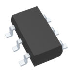 MAX25615AUT/V+T
The activity of extra discounts on wholesale prices is in full swing…
Please fill in your contact information and we will send you the latest wholesale price list.






