 ChipApex | Global Electronic Components Supplier
SEARCH
Search Product
Search Post
— IC芯片 | 连接器 | 传感器 | 被动器件 —
Search productSearch post
— IC芯片 | 连接器 | 传感器 | 被动器件 —
Consult the customer manager about the wholesale price.
consultation hotline:86-132-6715-2157
email:[email protected]
Contact the product manager for consultation. One-stop consultation is available.
Do you want a lower wholesale price? Please send us your inquiry and we will reply immediately.
The MAX4363EUP is a quad amplifier with shutdown, packaged in a 20-pin TSSOP. It operates from a single 5V supply (4.5V to 5.5V) and delivers up to +12.5dBm average line power for DMT signals. Key electrical parameters include a typical spurious-free dynamic range of -75dBc at 1MHz, a gain-bandwidth product of 190MHz, and a driver-to-receiver crosstalk of -95dB at 100kHz. The device features low voltage noise density of 8.5nV/√Hz and current noise density of 0.5pA/√Hz. It supports rail-to-rail output swing and includes thermal and short-circuit protection.
Verify the specific ordering suffix EUP corresponds to the 20-pin TSSOP package and industrial temperature range (-40°C to +85°C). Confirm that the component meets RoHS compliance requirements as indicated by the datasheet specifications. Ensure compatibility with existing PCB footprints for the TSSOP-20 package before procurement.
Select this component when a combined driver and receiver solution is required within a single package. The MAX4363 allows for external resistor setting of gain, offering design flexibility compared to fixed-gain alternatives. Consider the separate supply pins for driver and receiver sections to optimize noise performance in sensitive analog front-end designs.
The MAX4363EUP belongs to the MAX4361/MAX4362/MAX4363 family of high-performance ADSL drivers and receivers. While the MAX4361 offers a fixed-gain differential driver and the MAX4362 provides a dual amplifier, the MAX4363 integrates four amplifiers to serve as both the transmitter driver and receiver stages. This integration simplifies the design of full-rate ADSL customer premise equipment.
MAX4363ESP
Pulling the SHDN pin high places the amplifier outputs in a high-impedance disable mode and reduces supply current to approximately 70µA. Connect SHDN to GND for normal operation.
The device is capable of driving capacitive loads up to 2nF. For larger loads, isolation resistors should be used between the output and the load to reduce ringing.
A voltage divider using two equal-value resistors (e.g., 2.7kΩ) creates a reference voltage midway between the supply and ground. A decoupling capacitor (0.1µF) should be placed at this node.
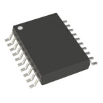 MAX4363EUP
The activity of extra discounts on wholesale prices is in full swing…
Please fill in your contact information and we will send you the latest wholesale price list.





