 ChipApex | Global Electronic Components Supplier
SEARCH
Search Product
Search Post
— IC芯片 | 连接器 | 传感器 | 被动器件 —
Search productSearch post
— IC芯片 | 连接器 | 传感器 | 被动器件 —
Consult the customer manager about the wholesale price.
consultation hotline:86-132-6715-2157
email:[email protected]
Contact the product manager for consultation. One-stop consultation is available.
Do you want a lower wholesale price? Please send us your inquiry and we will reply immediately.
The MAX44211ETP+ is a high-current differential line driver designed for powerline communication (PLC) applications. It delivers a linear output current of up to 1.5A and provides a peak-to-peak differential voltage swing of 36V. The device operates from an analog supply range of +8V to +20V and a digital supply range of +2.7V to +5.5V. It features programmable gain options of 6x, 12x, 15x, or 18x via G1 and G0 inputs. Integrated diagnostics include overtemperature shutdown at +160°C with 15°C hysteresis, a high-temperature warning at +150°C, and a programmable output current limit set by an external resistor. The component is housed in a 4mm x 4mm, 20-pin TQFN package.
Verify the specific ordering suffix against official manufacturer documentation to confirm lead-free compliance and package type. Confirm that the intended application environment remains within the specified -40°C to +85°C operating temperature range. Ensure proper thermal management strategies are implemented given the exposed pad requirement for heat dissipation.
Select this component when driving reactive loads typical of powerline networks requiring high peak currents. Evaluate the required gain setting based on input signal levels and transformer coupling requirements. Consider the trade-off between quiescent current consumption and linearity performance when configuring the MODE input for specific regional standards.
This part belongs to the MAX44211 family of high-current differential line drivers. It is specifically engineered for PLC environments where standard drivers cannot meet the current demands of coupling transformers. The device integrates protection mechanisms essential for robust operation in electrically noisy powerline environments.
Publicly confirmed substitute part numbers are not available in the provided documentation. Verify compatibility with existing board layouts if considering alternative devices, particularly regarding the 20-pin TQFN footprint and pinout configuration.
The output current limit is set using an external resistor connected between the ILSET pin and AGND. The resistance value determines the threshold according to the formula: I_LIM = 1 / (R_SET + 60), where R_SET is in kΩ and I_LIM is in amperes.
The MODE input selects the bias mode to balance linearity and power consumption. Leaving it unconnected selects low quiescent current mode suitable for CENELEC standards. Pulling it high selects higher quiescent current mode to improve linearity for FCC and ARIB standards.
The device monitors internal die temperature. If it exceeds +150°C, STATUS1 goes low to indicate a warning. If it reaches +160°C, both STATUS1 and STATUS0 go low, and the device enters automatic shutdown until the temperature drops below +145°C.
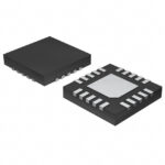 MAX44211ETP+
The activity of extra discounts on wholesale prices is in full swing…
Please fill in your contact information and we will send you the latest wholesale price list.





