 ChipApex | Global Electronic Components Supplier

SEARCH
Search Product
Search Post
— IC芯片 | 连接器 | 传感器 | 被动器件 —
Search productSearch post
— IC芯片 | 连接器 | 传感器 | 被动器件 —
Consult the customer manager about the wholesale price.
consultation hotline:86-132-6715-2157
email:[email protected]
Contact the product manager for consultation. One-stop consultation is available.
Do you want a lower wholesale price? Please send us your inquiry and we will reply immediately.
The MAX5389MAUD+ is a dual, 256-tap, volatile, low-voltage linear taper digital potentiometer manufactured by Analog Devices Inc./Maxim Integrated. It features an end-to-end resistance of 50kΩ and operates from a single +2.6V to +5.5V power supply. The device provides a low 35ppm/°C temperature coefficient and consumes less than 1μA of quiescent supply current. It utilizes an up/down interface for wiper control and sets the wiper to midscale upon power-on. The component is specified over an extended operating temperature range of -40°C to +125°C and is housed in a compact 14-pin TSSOP package.
Verify that the specific part number matches the required electrical characteristics, particularly the 50kΩ end-to-end resistance value associated with the 'M' suffix. Confirm the package type is 14-pin TSSOP and ensure compliance with RoHS standards as indicated by the '+' suffix. Cross-reference the manufacturer's documentation to confirm availability and lead times directly with authorized distributors or the manufacturer.
Select the MAX5389MAUD+ when a dual-channel digital potentiometer with a 50kΩ resistance value is required. Ensure the application supports volatile memory behavior, as wiper positions are lost upon power loss. Verify that the system voltage falls within the 2.6V to 5.5V range and that the up/down interface timing requirements are met by the host controller. Consider the -40°C to +125°C automotive temperature rating if operating in harsh environments.
The MAX5389MAUD+ belongs to the MAX5389 family of dual digital potentiometers. The 'M' suffix specifically denotes the 50kΩ end-to-end resistance variant, distinguishing it from the MAX5389LAUD+ (10kΩ) and MAX5389NAUD+ (100kΩ). All variants share identical pinouts, interfaces, and general specifications, differing only in their resistance values and associated continuous current ratings.
Direct replacements include MAX5389LAUD+ and MAX5389NAUD+. These parts share the same package and interface but differ in end-to-end resistance (10kΩ and 100kΩ, respectively). Verify that the circuit design can accommodate the different resistance values and that the continuous current limits for the replacement part are sufficient for the application load.
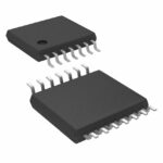 MAX5389MAUD+

The activity of extra discounts on wholesale prices is in full swing…
Please fill in your contact information and we will send you the latest wholesale price list.





