 ChipApex | Global Electronic Components Supplier

SEARCH
Search Product
Search Post
— IC芯片 | 连接器 | 传感器 | 被动器件 —
Search productSearch post
— IC芯片 | 连接器 | 传感器 | 被动器件 —
Consult the customer manager about the wholesale price.
consultation hotline:86-132-6715-2157
email:[email protected]
Contact the product manager for consultation. One-stop consultation is available.
Do you want a lower wholesale price? Please send us your inquiry and we will reply immediately.
The MAX5415EUD is a dual linear taper digital potentiometer from Maxim Integrated, housed in a 14-pin TSSOP package. It contains two independent 3-terminal potentiometers with 256 tap positions (8-bit resolution). The end-to-end resistance for each channel is nominally 100kΩ, with a typical range of 75kΩ to 125kΩ. Operating on a single supply voltage between +2.7V and +5.5V, the device draws an ultra-low supply current of 0.1µA at 2.7V. It features glitchless switching between resistor taps and a power-on reset that sets the wiper to midscale (position 128) upon initialization.
Verify the component marking against the datasheet pinout diagram to confirm authenticity. Ensure the operating environment remains within the specified -40°C to +85°C temperature range. Check that the supply voltage does not exceed the absolute maximum rating of +6V to prevent permanent damage. Confirm compatibility with the 3-wire SPI interface timing requirements before integration.
Select the MAX5415EUD when a nominal 100kΩ resistance value is required for the application. This model is suitable for designs needing low-drift performance with a ratiometric temperature coefficient of 5ppm/°C. It is appropriate for systems powered by single supplies between 2.7V and 5.5V where ultra-low standby current is critical. Consider the 14-pin TSSOP footprint constraints during PCB layout.
The MAX5415EUD belongs to the MAX5413/MAX5414/MAX5415 family of dual digital potentiometers. While the MAX5413 offers 10kΩ and the MAX5414 provides 50kΩ resistance values, the MAX5415 specifically delivers 100kΩ. All variants share identical packaging, pin configurations, and control interfaces, differing only in their internal resistor string values.
Direct replacements include the MAX5413EUD and MAX5414EUD, provided the circuit design can accommodate the lower 10kΩ or 50kΩ resistance values respectively. Other compatible parts must support the same 14-pin TSSOP package and 3-wire serial interface.
The POR circuitry automatically sets the wiper to the midscale position (code 128) at power-up, ensuring a known initial state.
The wiper position is controlled via a 3-wire serial interface consisting of Chip Select (CS), Data In (DIN), and Data Clock (SCLK).
The maximum Serial Clock (SCLK) frequency is guaranteed to be 10 MHz.
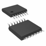 MAX5415EUD

The activity of extra discounts on wholesale prices is in full swing…
Please fill in your contact information and we will send you the latest wholesale price list.




