 ChipApex | Global Electronic Components Supplier

SEARCH
Search Product
Search Post
— IC芯片 | 连接器 | 传感器 | 被动器件 —
Search productSearch post
— IC芯片 | 连接器 | 传感器 | 被动器件 —
Consult the customer manager about the wholesale price.
consultation hotline:86-132-6715-2157
email:[email protected]
Contact the product manager for consultation. One-stop consultation is available.
Do you want a lower wholesale price? Please send us your inquiry and we will reply immediately.
The MAX5431AEUB+ is a digitally programmable precision resistor array designed for programmable-gain amplifier (PGA) applications. It provides four noninverting gain configurations of 1, 2, 4, and 8 with a ratio accuracy of 0.025%. The device operates from a single +15V or dual ±15V supply, consuming only 35µA of supply current. It features a CMOS/TTL logic compatible 2-wire parallel interface and includes an on-chip matching resistor for op amp input bias-current compensation. The component is housed in a space-saving 10-pin µMAX package and is specified over the extended temperature range of -40°C to +85°C.
Verify the specific ordering suffix 'U' corresponds to the 10-pin µMAX package and 'B' indicates the 0.09% accuracy grade if sourcing variants, though the primary model specifies 0.025% accuracy. Confirm the '+T' suffix denotes tape-and-reel packaging if applicable to the specific order code. Ensure compatibility with the required voltage range and temperature specifications for the target application environment.
Select the MAX5431 variant when op amp input bias-current compensation is required, as it includes a dedicated matching resistor network not present in the MAX5430. Choose the 'A' suffix version for applications demanding the highest precision at 0.025% ratio accuracy. Ensure the design accommodates the 10-pin µMAX footprint and the low supply current requirements of 35µA typical.
The MAX5431 is part of the MAX5430/MAX5431 family of digitally programmable high-precision resistor arrays. While the MAX5430 lacks the internal matching resistor, the MAX5431 integrates this feature specifically to compensate for offset voltages caused by op amp input bias currents. Both devices share identical gain settings and interface protocols but differ in their suitability for different op amp types based on bias current characteristics.
The MAX5430AEUB+ serves as a direct functional substitute if the on-chip matching resistor is unnecessary and an ultra-low input bias current op amp is used instead. Verify that the replacement maintains the same 0.025% accuracy grade and 10-pin µMAX package form factor.
These pins connect to an on-chip matching resistor equal to the impedance seen at the W terminal for gains of 2, 4, and 8. This resistor compensates for offset voltage due to op amp input bias currents.
Gain is set via a simple two-bit parallel digital interface using inputs D0 and D1. The logic table defines gains of 1, 2, 4, and 8 for binary inputs 00, 01, 10, and 11 respectively.
The resistance between the High (H) and Low (L) terminals is fixed at 57 kΩ.
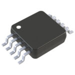 MAX5431AEUB+

The activity of extra discounts on wholesale prices is in full swing…
Please fill in your contact information and we will send you the latest wholesale price list.





