 ChipApex | Global Electronic Components Supplier

SEARCH
Search Product
Search Post
— IC芯片 | 连接器 | 传感器 | 被动器件 —
Search productSearch post
— IC芯片 | 连接器 | 传感器 | 被动器件 —
Consult the customer manager about the wholesale price.
consultation hotline:86-132-6715-2157
email:[email protected]
Contact the product manager for consultation. One-stop consultation is available.
Do you want a lower wholesale price? Please send us your inquiry and we will reply immediately.
The MAX5431CEUB+ is a digitally programmable precision resistor array designed for programmable-gain amplifier (PGA) applications. It operates from single +12V to +15V or dual ±12V to ±15V supplies, consuming only 35µA of supply current. The device provides four noninverting gain configurations (1, 2, 4, and 8) with a ratio accuracy of 0.5%. It features a CMOS/TTL logic compatible 2-wire parallel interface and includes an on-chip matching resistor for op amp input bias-current compensation. The component is housed in a space-saving 10-pin µMAX package and is specified over the extended temperature range of -40°C to +85°C.
Verify that the specific order suffix 'CEUB+' corresponds to the C-grade accuracy (0.5%) and the 10-pin µMAX package as documented in the official Analog Devices/Maxim Integrated datasheet. Confirm that the '+'' indicates lead-free compliance if required by the application standards. Ensure the operating environment remains within the specified -40°C to +85°C temperature range.
Select the MAX5431CEUB+ when a 0.5% divider ratio accuracy is sufficient for the target PGA design. This variant is appropriate for applications requiring on-chip bias-current compensation via the matching resistor. Compare against the A and B grades if tighter accuracy (0.025% or 0.09%) is necessary, noting that those variants may have different cost implications. Ensure the system power supply supports the required ±15V or single 15V operation.
The MAX5431CEUB+ belongs to the MAX5430/MAX5431 family of digitally programmable high-precision resistor arrays. While the MAX5430 lacks the internal matching resistor, the MAX5431 includes it specifically to compensate for offset voltage caused by op amp input bias currents. This family is engineered for space-constrained designs using SOT23 or µMAX packages.
The MAX5430CEUB+ serves as a direct substitute if the on-chip matching resistor is not required and the designer plans to use an ultra-low input bias current op amp instead. Other grade variations (AEUB+, BEUB+) offer higher accuracy but do not change the pinout or basic functionality.
These pins connect to an on-chip matching resistor used to compensate for the offset voltage due to the input bias current of the operational amplifier.
The gain is set via a simple two-bit parallel programming interface using digital inputs D0 and D1, corresponding to gains of 1, 2, 4, or 8.
The resistance between the High (H) and Low (L) terminals is typically 57 kΩ.
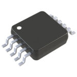 MAX5431CEUB+

The activity of extra discounts on wholesale prices is in full swing…
Please fill in your contact information and we will send you the latest wholesale price list.





