 ChipApex | Global Electronic Components Supplier

SEARCH
Search Product
Search Post
— IC芯片 | 连接器 | 传感器 | 被动器件 —
Search productSearch post
— IC芯片 | 连接器 | 传感器 | 被动器件 —
Consult the customer manager about the wholesale price.
consultation hotline:86-132-6715-2157
email:[email protected]
Contact the product manager for consultation. One-stop consultation is available.
Do you want a lower wholesale price? Please send us your inquiry and we will reply immediately.
The MAX6361LUT44+T is a low-power microprocessor supervisory circuit manufactured by Analog Devices Inc. under the Maxim Integrated brand. It operates within a supply voltage range of 1.2V to 5.5V and features a fixed reset threshold voltage of 4.40V. The device provides an active-high, open-drain reset output with a typical delay time of 280ms. It includes a manual reset input and a battery backup switch for extended functionality. Packaged in a compact SOT-23-6 surface-mount format, it supports operation across a temperature range of -40°C to +85°C.
Verify component authenticity through authorized distributors or direct manufacturer channels due to potential availability constraints. Confirm package marking and date codes against official documentation. Ensure storage conditions comply with moisture sensitivity levels specified in the datasheet. Cross-reference part numbers carefully as suffixes may indicate tape-and-reel packaging variations. Request lot traceability certificates if required for quality assurance protocols.
Evaluate the fixed 4.40V threshold against target system voltage requirements to ensure proper reset triggering. Consider the active-high output polarity compatibility with downstream logic inputs. Assess the need for manual reset capability versus automatic-only supervision. Review thermal performance specifications relative to expected ambient operating conditions. Compare quiescent current consumption against battery life requirements for portable applications.
This component belongs to the MAX6361 series of low-power microprocessor supervisors designed for critical voltage monitoring tasks. The series offers various threshold options and output configurations to suit different system architectures. Manufactured using advanced CMOS processes, these devices emphasize low power consumption and high reliability. The specific model integrates standard supervisory functions with additional manual reset and backup capabilities for enhanced system control flexibility.
Consult official cross-reference guides for electrically equivalent alternatives with matching threshold voltages and output polarities. Verify pinout compatibility to avoid PCB redesign requirements when substituting components. Ensure replacement parts meet identical temperature range and package dimension specifications. Confirm that any substitute maintains the same manual reset and battery backup functionality if present in the original design.
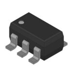 MAX6361LUT44+

The activity of extra discounts on wholesale prices is in full swing…
Please fill in your contact information and we will send you the latest wholesale price list.





