 ChipApex | Global Electronic Components Supplier
SEARCH
Search Product
Search Post
— IC芯片 | 连接器 | 传感器 | 被动器件 —
Search productSearch post
— IC芯片 | 连接器 | 传感器 | 被动器件 —
Consult the customer manager about the wholesale price.
consultation hotline:86-132-6715-2157
email:[email protected]
Contact the product manager for consultation. One-stop consultation is available.
Do you want a lower wholesale price? Please send us your inquiry and we will reply immediately.
The MAX7415EPA+ is a 5th-order, lowpass, elliptic switched-capacitor filter operating from a single +3V supply. It features a transition ratio of 1.25 and provides 37dB of stopband rejection. The device draws 1.2mA in operating mode and reduces to 0.2µA in shutdown mode. It supports corner frequencies from 1Hz to 15kHz via internal or external clocking. Key electrical parameters include ±4mV output offset voltage, -80dB THD plus noise, and a maximum capacitive load of 500pF at the output.
Verify the specific suffix 'EPA+' against the manufacturer's current ordering guide to confirm the package type, temperature range, and lead-free status. Ensure the component meets RoHS compliance requirements for your assembly process. Cross-reference the datasheet revision date to validate all electrical characteristics before finalizing procurement specifications.
Select the MAX7415EPA+ when a single +3V supply is required alongside a steep transition ratio of 1.25. This model is appropriate for applications needing 37dB stopband rejection. Compare against the MAX7408 if higher stopband rejection is prioritized over rolloff steepness. Verify that the 15kHz maximum corner frequency aligns with the system bandwidth requirements.
This component belongs to the MAX7408/MAX7411/MAX7412/MAX7415 family of 5th-order elliptic switched-capacitor filters. The MAX7415 variant is specifically designed for +3V operation, distinguishing it from the +5V MAX7408 and MAX7411 models within the same series.
The MAX7408 serves as a functional substitute for similar filtering tasks but requires a +5V supply instead of +3V. Designers must account for the difference in transition ratios (1.6 vs 1.25) and stopband rejection levels when swapping between these variants.
The corner frequency is set by the clock frequency using a 100:1 ratio. It can be controlled via an external clock source or an internal oscillator defined by an external capacitor connected to the CLK pin.
The OS (Offset Adjust) pin allows for the adjustment of the DC output level. It should be connected to COM if no offset adjustment is needed, or biased with a resistive divider for DC level shifting.
Driving the SHDN pin low activates shutdown mode, reducing supply current to 0.2µA and placing the output in a high-impedance state. Driving SHDN high or connecting it to VDD returns the device to normal operation.
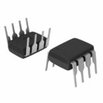 MAX7415EPA+
The activity of extra discounts on wholesale prices is in full swing…
Please fill in your contact information and we will send you the latest wholesale price list.





