 ChipApex | Global Electronic Components Supplier

SEARCH
Search Product
Search Post
— IC芯片 | 连接器 | 传感器 | 被动器件 —
Search productSearch post
— IC芯片 | 连接器 | 传感器 | 被动器件 —
Consult the customer manager about the wholesale price.
consultation hotline:86-132-6715-2157
email:[email protected]
Contact the product manager for consultation. One-stop consultation is available.
Do you want a lower wholesale price? Please send us your inquiry and we will reply immediately.
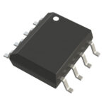
MC100LVEL32DR2 is listed in the Counter Dividers range at ChipApex. The manufacturer field lists onsemi. Its product description is IC DIVIDER DIV X2 3.3V 8-SOIC. Review the specifications below when checking this part for your BOM.
The MC100LVEL32DR2G is a 3.3 V ECL ÷2 divider from onsemi, packaged in SOIC-8 NB with a tape and reel shipping format. It features a propagation delay of 510 ps and a typical maximum toggle frequency of 2.6 GHz. The device operates within a PECL mode range of VCC = 3.0 V to 3.8 V (VEE = 0 V) or an NECL mode range of VEE = -3.0 V to -3.8 V (VCC = 0 V). Power supply current ranges from 29 mA to 36 mA across the operating temperature range of -40°C to +85°C.
Verify the specific package suffix against the datasheet ordering information to ensure correct physical dimensions and shipping configuration. Confirm RoHS compliance status and Pb-Free marking requirements for your assembly process. Check for any recent Product Change Notices regarding manufacturing site transfers or material updates before finalizing procurement specifications.
Select this component when a 3.3 V low-voltage ECL interface is required for ÷2 frequency division. Ensure the application supports differential clock inputs or utilizes the internal VBB reference for single-ended configurations. Verify that the power supply architecture aligns with either PECL or NECL operating modes to meet the specified voltage ranges.
This part belongs to the MC100LVEL32 series of integrated dividers designed for low-voltage ECL applications. It is functionally identical to the EL32 but optimized for 3.3 V operation. The series provides high-speed performance with internal temperature compensation, making it suitable for demanding timing-critical environments where stable frequency division is essential.
MC100EL32DT
Connect the unused differential input to the VBB pin, which serves as the switching reference voltage. Decouple VBB and VCC with a 0.01 µF capacitor and limit current sourcing or sinking to 0.5 mA.
Upon power-up, the internal flip-flop attains a random state. The asynchronous reset pin must be used to synchronize the device and establish a known initial state.
Explore related parts through Logic, Integrated Circuits (ICs), all product categories, ChipApex homepage.
 MC100LVEL32DR2

The activity of extra discounts on wholesale prices is in full swing…
Please fill in your contact information and we will send you the latest wholesale price list.





