 ChipApex | Global Electronic Components Supplier

SEARCH
Search Product
Search Post
— IC芯片 | 连接器 | 传感器 | 被动器件 —
Search productSearch post
— IC芯片 | 连接器 | 传感器 | 被动器件 —
Consult the customer manager about the wholesale price.
consultation hotline:86-132-6715-2157
email:[email protected]
Contact the product manager for consultation. One-stop consultation is available.
Do you want a lower wholesale price? Please send us your inquiry and we will reply immediately.
The MC74LVX4051MELG is an analog multiplexer/demultiplexer manufactured by onsemi, utilizing high-performance silicon-gate CMOS technology. It features a single-pole eight-throw (SP8T) configuration with three digital channel-select inputs and an active-high enable input. The device operates within a digital power supply range of 2.5 V to 6.0 V and supports analog signals across the full supply range from VCC to VEE. Key electrical characteristics include a maximum ON resistance of 86 Ω at 3.0 V, propagation delays up to 40 ns, and a bandwidth of 80 MHz. It is housed in a 16-pin SOEIAJ package.
Verify the specific ordering suffix ELG corresponds to the SOEIAJ-16 package and tape-and-reel quantity of 2000 units as documented in the official datasheet. Confirm RoHS compliance status and ensure the component meets the required operating temperature range of -55°C to +125°C for your specific application environment.
Select this component when an 8-channel analog switch is required with low ON resistance and high linearity. Ensure the system voltage falls within the 2.5 V to 6.0 V digital supply range. Consider the SOEIAJ-16 package dimensions if board space is constrained, and verify that the 80 MHz bandwidth meets the signal frequency requirements.
This part belongs to the MC74LVX4051 series of analog multiplexers. It shares pinout compatibility with HC4051A and metal-gate MC14051B devices but offers superior performance metrics due to its silicon-gate CMOS construction. The M suffix indicates the SOEIAJ-16 package type, while ELG denotes the specific reel packaging configuration.
Direct pin-compatible replacements include the MC74HC4051 and MC14051B, though these may exhibit higher ON resistance and different linearity characteristics. For equivalent performance, consider other LVX series variants such as the MC74LVXT4051, ensuring package and electrical specifications match the design requirements.
The analog inputs/outputs can swing between the positive supply voltage (VCC) and the negative supply voltage (VEE), provided the difference between VCC and VEE does not exceed 6.0 V.
Unused analog inputs/outputs may be left floating. However, tying them to VCC or GND through a low-value resistor is recommended to minimize crosstalk and feedthrough noise.
Yes, the Channel-Select and Enable inputs are overvoltage tolerant (OVT), allowing for level translation from 6.0 V down to 3.0 V logic levels.
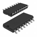 MC74LVX4051MELG

The activity of extra discounts on wholesale prices is in full swing…
Please fill in your contact information and we will send you the latest wholesale price list.





