 ChipApex | Global Electronic Components Supplier

SEARCH
Search Product
Search Post
— IC芯片 | 连接器 | 传感器 | 被动器件 —
Search productSearch post
— IC芯片 | 连接器 | 传感器 | 被动器件 —
Consult the customer manager about the wholesale price.
consultation hotline:86-132-6715-2157
email:[email protected]
Contact the product manager for consultation. One-stop consultation is available.
Do you want a lower wholesale price? Please send us your inquiry and we will reply immediately.
The MC74LVXT4053MG is a high-performance silicon-gate CMOS analog multiplexer/demultiplexer manufactured by onsemi. It features three independent single-pole double-throw (SPDT) switches with common off functionality, housed in a 16-pin SOEIAJ package. The device operates within a digital supply voltage range of 2.5 V to 6.0 V and supports an analog power supply range from -3.0 V to +3.0 V relative to ground. Key electrical characteristics include a maximum ON resistance of 86 Ohms at 3.0 V and 26 Ohms at 4.5 V, propagation delays of 40 ns at 2.5 V, and a bandwidth of 80 MHz. It offers low leakage currents, break-before-make switching, and TTL-compatible control inputs.
Verify the specific ordering suffix 'M' corresponds to the SOEIAJ-16 package configuration required for your design. Confirm that the component meets RoHS compliance standards if environmental regulations apply to your manufacturing process. Ensure that the lead pitch and thermal characteristics of the SOEIAJ-16 package are compatible with your PCB footprint and assembly capabilities.
Select this component when a triple SPDT analog switch with TTL-compatible controls is required. It is suitable for applications needing operation across a wide analog voltage range defined by VCC and VEE supplies. Consider the 86 Ohm maximum ON resistance at lower voltages when designing for low-loss signal paths. Verify that the 125°C maximum operating temperature aligns with your system's thermal environment.
This part belongs to the MC74LVXT4053 series of analog multiplexers. It shares pinout compatibility with LVX8053, HC4053A, and MC14053B devices, facilitating drop-in replacements in existing designs. The MG suffix specifically denotes the SOEIAJ-16 package variant, distinguishing it from SOIC or TSSOP versions within the same logical family.
Direct pin-compatible alternatives include MC74LVXT4053DTR2G (SOIC-16) and MC74LVXT4053DT (TSSOP-16). For non-pin-compatible swaps, consider SN74LV4053ATPWREP from Texas Instruments, noting differences in supply voltage limits and package dimensions.
When the Enable pin is held HIGH, all three analog switches are turned off, placing the outputs in a high-impedance state regardless of the Channel-Select inputs.
The analog voltage can vary across the complete power supply range, from VEE to VCC. The positive peak should not exceed VCC, and the negative peak should not go below VEE.
No, the ON resistance varies with the input voltage. It is more linear than metal-gate CMOS switches but still exhibits variation, with maximum values specified at different VCC voltages in the datasheet.
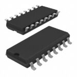 MC74LVXT4053MG

The activity of extra discounts on wholesale prices is in full swing…
Please fill in your contact information and we will send you the latest wholesale price list.





