 ChipApex | Global Electronic Components Supplier

SEARCH
Search Product
Search Post
— IC芯片 | 连接器 | 传感器 | 被动器件 —
Search productSearch post
— IC芯片 | 连接器 | 传感器 | 被动器件 —
Consult the customer manager about the wholesale price.
consultation hotline:86-132-6715-2157
email:[email protected]
Contact the product manager for consultation. One-stop consultation is available.
Do you want a lower wholesale price? Please send us your inquiry and we will reply immediately.
The MC74VHC4051DTR2G is a single-pole, eight-position analog multiplexer/demultiplexer manufactured by onsemi using silicon-gate CMOS technology. It operates with a digital supply voltage (VCC) ranging from 2.0 V to 6.0 V and an analog supply range (VCC - VEE) of 2.0 V to 12.0 V. The device features a maximum ON resistance of 100 Ω at VCC = 6.0 V and VEE = 0 V, with a channel-to-channel matching of 10 Ω. It provides a bandwidth of 80 MHz and off-channel leakage current of 1.0 μA at 125°C. Packaged in a 16-TSSOP case 948F, it supports surface-mount installation.
Verify the specific ordering suffix 'DT' corresponds to the TSSOP-16 package configuration required for your design. Confirm that the 'G' suffix indicates a lead-free, halogen-free, and RoHS-compliant package status as specified in the manufacturer's documentation before finalizing procurement orders.
Select this component when a single 8:1 analog switch is needed within a 2V to 6V digital logic environment. Ensure the analog signal swing remains within the VCC to VEE limits. Consider the 100 Ω ON resistance and 80 MHz bandwidth specifications against your circuit requirements for signal integrity and speed.
This part belongs to the MC74VHC405x family, which includes the dual 4-position (MC74VHC4052) and triple 2-position (MC74VHC4053) variants. All devices share identical pinouts and core technology but differ in the number of independent switches provided per package.
The MC74VHC4051DR2G serves as a direct replacement offering the same functionality in a 16-SOIC package instead of the TSSOP-16 form factor. Verify footprint compatibility if substituting between these two package types.
When the Enable pin is held HIGH, all analog switches are turned off, isolating the common output/input from the selected channels.
The analog signals must vary across the complete power supply range, from VEE to VCC. The positive peak should not exceed VCC and the negative peak should not go below VEE.
Yes, the Channel-Select and Enable inputs are compatible with LSTTL outputs when external pull-up resistors are utilized.
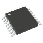 MC74VHC4051DTR2G

The activity of extra discounts on wholesale prices is in full swing…
Please fill in your contact information and we will send you the latest wholesale price list.





