 ChipApex | Global Electronic Components Supplier

SEARCH
Search Product
Search Post
— IC芯片 | 连接器 | 传感器 | 被动器件 —
Search productSearch post
— IC芯片 | 连接器 | 传感器 | 被动器件 —
Consult the customer manager about the wholesale price.
consultation hotline:86-132-6715-2157
email:[email protected]
Contact the product manager for consultation. One-stop consultation is available.
Do you want a lower wholesale price? Please send us your inquiry and we will reply immediately.
The MC74VHC4053DTR2 is a triple single-pole double-throw (SPDT) analog multiplexer/demultiplexer manufactured by onsemi. It utilizes high-performance silicon-gate CMOS technology to achieve fast propagation delays, low ON resistance, and low OFF leakage currents. The device features three independent SPDT switches controlled by digital select inputs A, B, and C, along with an active-high Enable pin that turns all switches off when HIGH. It supports analog signal voltages ranging from VEE to VCC, allowing for dual supply operation between -6.0 V and +12.0 V relative to ground, or single supply operation from 2.0 V to 6.0 V. The component is housed in a 16-pin TSSOP package.
Verify the specific ordering suffix 'R2' corresponds to the tape and reel packaging configuration required for automated assembly processes. Confirm that the TSSOP-16 package dimensions align with the target PCB footprint and reflow soldering profiles. Ensure the component meets RoHS compliance standards if restricted materials are prohibited in the final assembly.
Select this component when three independent SPDT analog switching paths are required within a single integrated circuit. The VHC series offers faster switching speeds and lower power consumption compared to legacy HC or HCT families. Consider the maximum ON resistance variations across temperature ranges and ensure the analog signal swing remains within the specified VCC and VEE boundaries to prevent excessive current draw.
This part belongs to the MC74VHC405x family, which includes the MC74VHC4051 (8-channel) and MC74VHC4052 (4-channel). All devices share identical pinouts with the older HC405xA and metal-gate MC1405xB series, facilitating direct pin-compatible upgrades. The VHC designation indicates high-speed CMOS performance with a wider operating voltage range than standard logic families.
MC74VHC4053DR2G
The Enable pin is active-high. When the Enable input is HIGH, all three analog switches are turned off, isolating the common outputs/inputs from the channel inputs/outputs. When LOW, the switches operate according to the state of the Channel-Select inputs.
The analog signals can vary across the complete power supply range from VEE to VCC. With recommended operating conditions, VCC can range from 2.0 V to 6.0 V (relative to GND) and VEE from -6.0 V to GND, allowing a total analog swing of up to 12.0 V peak-to-peak.
No. Unused digital inputs (Channel-Select or Enable) must always be tied to an appropriate logic voltage level (either GND or VCC). Floating inputs can lead to unpredictable behavior or increased power consumption due to internal threshold crossing.
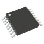 MC74VHC4053DTR2

The activity of extra discounts on wholesale prices is in full swing…
Please fill in your contact information and we will send you the latest wholesale price list.





