 ChipApex | Global Electronic Components Supplier

SEARCH
Search Product
Search Post
— IC芯片 | 连接器 | 传感器 | 被动器件 —
Search productSearch post
— IC芯片 | 连接器 | 传感器 | 被动器件 —
Consult the customer manager about the wholesale price.
consultation hotline:86-132-6715-2157
email:[email protected]
Contact the product manager for consultation. One-stop consultation is available.
Do you want a lower wholesale price? Please send us your inquiry and we will reply immediately.
MCP795B11-I/SL is listed in the Real Time Clock range at ChipApex. The manufacturer field lists Microchip Technology. Its product description is IC RTC CLK/CALENDAR SPI 14SOIC. Review the specifications below when checking this part for your BOM.
The MCP795B11-I/SL is a low-power Real-Time Clock/Calendar (RTCC) from Microchip Technology, featuring an SPI interface. It includes 64 bytes of battery-backed SRAM and 1 Kbit of EEPROM with preprogrammed EUI-48™ Unique ID. Key electrical parameters include a VCC operating range of 1.8V to 5.5V and a VBAT range of 1.3V to 5.5V. Standby current is less than 1µA at 3V, while timekeeping current on VBAT is under 700nA at 1.8V. The device supports industrial temperature operation (-40°C to +85°C) and provides features such as programmable alarms, watchdog timer, event detection, and automatic battery switchover.
Verify the package suffix 'SL' corresponds to the TSSOP-14 form factor, as datasheet documentation primarily references SOIC/TSSOP generic designations. Confirm that the specific revision matches the preliminary DS22280A specifications regarding the 32 kHz boot feature unique to the BXX series. Ensure compatibility with the required external 32,768 kHz tuning fork crystal and load capacitors for oscillator operation.
Select this model over the WXX series if a 32 kHz clock output at power-up is required for system initialization. The '11' designation indicates 1 Kbit EEPROM capacity; choose '21' variants if 2 Kbit storage is needed. Verify that the preprogrammed EUI-48™ ID meets network identification requirements, or select 'Blank' variants if custom programming is preferred. Ensure the SPI interface speed up to 10 MHz aligns with the master controller's capabilities.
This component belongs to the MCP795WXX/MCP795BXX family of stand-alone RTCC devices. The 'B' prefix distinguishes it from the 'W' series by adding the 32 kHz boot-up clock capability. The 'I' suffix denotes the Industrial temperature grade (-40°C to +85°C). These devices are designed to reduce component counts in applications requiring accurate timekeeping and non-volatile data storage with minimal power consumption.
Public confirmed substitute part numbers: MCP795B11-I/ST (SOIC-14 package variant), MCP795B11T-I/SL (Tape & Reel packaging variant).
On MCP795BXX devices, the CLKOUT/BOOT pin provides a 32 kHz clock output specifically at power-up. Under normal operation, it functions as a programmable square wave output (1Hz, 4.096kHz, 8.192kHz, or 32.768kHz).
The device features an automatic battery switchover circuit. When VCC drops below the trip voltage (typically 1.5V), it switches to VBAT to maintain timekeeping and SRAM retention. It also logs power-down and power-up timestamps to calculate failure duration.
It contains 64 bytes of battery-backed SRAM for user data and 1 Kbit of Serial EEPROM. The EEPROM includes a protected 128-bit area preprogrammed with an EUI-48™ Unique ID.
Explore related parts through Clock/Timing, Integrated Circuits (ICs), all product categories, ChipApex homepage.
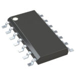 MCP795B11-I/SL

The activity of extra discounts on wholesale prices is in full swing…
Please fill in your contact information and we will send you the latest wholesale price list.





