ChipApex | Global Electronic Components Supplier

SEARCH
Search Product
Search Post
— IC芯片 | 连接器 | 传感器 | 被动器件 —
Search productSearch post
— IC芯片 | 连接器 | 传感器 | 被动器件 —
Consult the customer manager about the wholesale price.
consultation hotline:86-132-6715-2157
email:[email protected]
Contact the product manager for consultation. One-stop consultation is available.
Do you want a lower wholesale price? Please send us your inquiry and we will reply immediately.
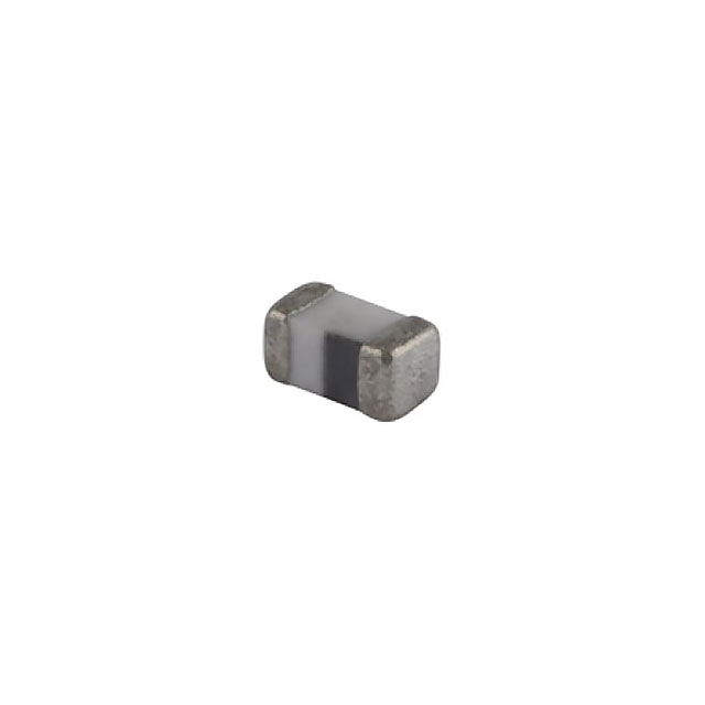
The MFBM1V1005-801-R is a multilayer ferrite chip bead designed for EMI suppression in power line applications. Manufactured by Eaton Electronics Division, this component features a single-line configuration housed in a compact 0402 (1005 metric) surface-mount package with dimensions of 1.00mm x 0.50mm and a maximum height of 0.65mm. It provides an impedance of 800 Ohms at 100 MHz with a tolerance of ±25%. The device supports a maximum DC current of 300mA and exhibits a maximum DC resistance of 650 milliohms. It operates within a temperature range of -40°C to +85°C and complies with RoHS3 standards.
Verify the specific impedance value and current rating against the official Eaton datasheet before integration. Confirm that the 0402 package dimensions align with your PCB footprint requirements. Ensure the operating temperature range meets your environmental specifications. Check for RoHS3 compliance if required by your manufacturing standards. Validate the supplier's authenticity to avoid counterfeit components.
Select this component when high impedance at 100 MHz is required for a single power line in a small form factor. The 300mA current rating suits low-power circuits. Consider the 650 milliohm DC resistance impact on voltage drop. Compare with other MFBM1V series variants if higher current handling or different impedance characteristics are needed. Ensure the surface-mount technology matches your assembly capabilities.
This part belongs to the MFBM1V series of multilayer ferrite chip beads from Eaton Electronics Division. The series offers various impedance values and current ratings in standard metric packages. These components are engineered for EMI suppression in modern electronic systems where space is limited. The MFBM1V1005-801-R specifically targets applications requiring 800 Ohms impedance in a 0402 case size.
Direct substitutes include other MFBM1V1005 variants with similar impedance, such as MFBM1V1005-800-R (80 Ohms) or MFBM1V1005-102-R (1000 Ohms), provided the impedance difference is acceptable. Verify current ratings and DC resistance for any cross-replacement to ensure circuit performance remains unaffected.
 MFBM1V1005-801-R

The activity of extra discounts on wholesale prices is in full swing…
Please fill in your contact information and we will send you the latest wholesale price list.