 ChipApex | Global Electronic Components Supplier

SEARCH
Search Product
Search Post
— IC芯片 | 连接器 | 传感器 | 被动器件 —
Search productSearch post
— IC芯片 | 连接器 | 传感器 | 被动器件 —
Consult the customer manager about the wholesale price.
consultation hotline:86-132-6715-2157
email:[email protected]
Contact the product manager for consultation. One-stop consultation is available.
Do you want a lower wholesale price? Please send us your inquiry and we will reply immediately.
The MK2746GTR is a DVD/MPEG clock synthesizer manufactured by Integrated Device Technology (IDT), now part of Renesas Electronics. It utilizes analog Phase-Locked Loop (PLL) techniques to generate multiple output clocks from a 27 MHz fundamental mode crystal or clock input. The device provides selectable processor and audio clocks, alongside fixed outputs for video (27 MHz), bus driver (50 MHz), and SDRAM (133.33 MHz). Designed for MPEG-2 applications, it employs patented zero ppm error techniques to frequency-lock audio clocks to the 27 MHz input, ensuring precise audio-video synchronization without requiring large buffer memory.
Verify component authenticity as IDT was acquired by Renesas Electronics. Confirm RoHS compliance status, noting that non-green parts reached End-of-Life on May 13, 2010. Ensure the GTR suffix corresponds to tape and reel packaging requirements for your assembly line. Check current availability as this is a legacy component.
Select the MK2746GTR when designing MPEG-2 systems requiring tight jitter control and specific fixed frequencies like 133.33 MHz for SDRAM. Use the PS1/PS0 pins to configure processor clock speeds (6.66, 41.66, 50, or 58.33 MHz) and AS1/AS0 pins for audio sampling rates (12.288, 11.2896, 18.432, or 8.192 MHz). Ensure the design supports a 27 MHz crystal input and 3.3 V power supply.
The MK2746 is part of IDT's DVD/MPEG clock synthesizer family, designed to replace traditional oscillators and VCXOs in multimedia boards. The 'G' suffix typically denotes lead-free/RoHS compliant versions, while 'TR' indicates tape and reel shipping. This component simplifies board design by integrating multiple clock functions into a single chip.
Consult IDT/Renesas for direct replacements if non-green parts are obsolete. Similar devices in the IDT portfolio include the MK2745 and MK2746 variants, though pinouts and specific fixed outputs may differ. Verify compatibility with existing PCB layouts and crystal specifications.
Processor clock frequency is selected via pins PS1 and PS0, offering options of 6.66, 41.66, 50, or 58.33 MHz. Audio clock frequency is selected via pins AS1 and AS0, providing 12.288, 11.2896, 18.432, or 8.192 MHz.
The device provides three fixed output clocks: 27 MHz for Video (Pin 15), 50 MHz for DSP/Bus clock (Pin 9), and 133.33 MHz for SDRAM (Pin 7).
A 0.01µF decoupling capacitor should be connected between VDD and GND as close to the device as possible, mounted on the component side of the PCB without using vias in the decoupling circuit.
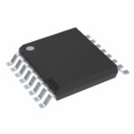 MK2746GTR

The activity of extra discounts on wholesale prices is in full swing…
Please fill in your contact information and we will send you the latest wholesale price list.






