 ChipApex | Global Electronic Components Supplier
SEARCH
Search Product
Search Post
— IC芯片 | 连接器 | 传感器 | 被动器件 —
Search productSearch post
— IC芯片 | 连接器 | 传感器 | 被动器件 —
Consult the customer manager about the wholesale price.
consultation hotline:86-132-6715-2157
email:[email protected]
Contact the product manager for consultation. One-stop consultation is available.
Do you want a lower wholesale price? Please send us your inquiry and we will reply immediately.
The MMBZ5221BS-7-F is a dual isolated Zener diode array manufactured by Diodes Incorporated, housed in an SOT-363 surface-mount package. It features a nominal Zener voltage of 2.4 V with a tolerance range of 2.28 V to 2.52 V at a test current of 20 mA. The device supports a maximum power dissipation of 200 mW and operates within a temperature range of -65°C to +150°C. Electrical specifications include a maximum Zener impedance of 30 Ohms at the test current and a maximum reverse leakage current of 100 µA at 1.0 V. The forward voltage is rated at 0.9 V when tested at 10 mA.
Verify component authenticity through official manufacturer channels or authorized distributors. Confirm that the ordering suffix matches the required packaging configuration. Ensure compliance with RoHS directives and check date codes for green molding compound requirements if halogen-free status is critical for the specific application environment.
Select this component when a dual Zener configuration is required in a minimal footprint. Compare electrical parameters such as Zener impedance and leakage current against circuit requirements. Verify thermal resistance characteristics and ensure adequate pad layout on the FR4 PCB to support the recommended 200 mW power dissipation limit during operation.
This part belongs to the MMBZ5221BS-MMBZ5259BS series, which provides various Zener voltage options within the same SOT-363 package. The series utilizes a consistent mechanical outline and marking scheme across different voltage ratings, facilitating design standardization for multi-voltage reference needs in space-constrained electronics.
Direct substitutes include other MMBZ5221BS variants from Diodes Incorporated with identical electrical characteristics. Cross-referencing requires matching the SOT-363 package dimensions and verifying equivalent Zener voltage tolerances and power dissipation limits.
The maximum reverse leakage current is 100 µA when measured at a reverse voltage of 1.0 V.
The marking consists of a product type code (KC1) followed by a date code indicating the year and month of manufacture.
The thermal resistance (RθJA) is 625 °C/W when mounted on an FR4 PCB with the recommended pad layout.
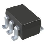 MMBZ5221BS-7-F
The activity of extra discounts on wholesale prices is in full swing…
Please fill in your contact information and we will send you the latest wholesale price list.




