 ChipApex | Global Electronic Components Supplier

SEARCH
Search Product
Search Post
— IC芯片 | 连接器 | 传感器 | 被动器件 —
Search productSearch post
— IC芯片 | 连接器 | 传感器 | 被动器件 —
Consult the customer manager about the wholesale price.
consultation hotline:86-132-6715-2157
email:[email protected]
Contact the product manager for consultation. One-stop consultation is available.
Do you want a lower wholesale price? Please send us your inquiry and we will reply immediately.
The NB2308AI2DG is a 3.3 V zero delay clock buffer manufactured by onsemi, designed for high-speed clock distribution in industrial environments (-40°C to 85°C). It features an internal PLL that locks to a reference input (REF) and provides eight buffered outputs divided into two banks of four. The device supports an input frequency range of 15 MHz to 133 MHz with a maximum operating frequency of 133.3 MHz. Key electrical specifications include an input-to-output propagation delay of less than 250 ps, output-to-output skew under 200 ps, and cycle-to-cycle jitter below 200 ps at 66.67 MHz. It operates on a 3.0 V to 3.6 V supply and utilizes advanced 0.35 µm CMOS technology.
Verify component authenticity through authorized distributors or official manufacturer channels. Confirm the specific suffix 'I2DG' corresponds to the Industrial temperature grade, SOIC-16 package, and Pb-free status as defined in the ordering information table. Cross-reference the datasheet revision date (Nov05 Rev 2) to ensure compatibility with current design requirements.
Select the NB2308AI2DG when an industrial temperature range (-40°C to 85°C) is required alongside a 2X/1X frequency configuration. Ensure the PCB layout maintains equal capacitive loading on all outputs and the FBK pin to achieve zero delay characteristics. Verify that the load capacitance does not exceed 15 pF for frequencies above 100 MHz to maintain specified rise/fall times and jitter performance.
This component belongs to the NB2308A family of 3.3 V zero delay buffers. The 'I' suffix denotes the Industrial temperature rating, while '2' specifies the frequency multiplication configuration (2X/1X). The 'DG' suffix indicates a Pb-free SOIC-16 package. Other variants in the series include commercial grades ('C'), different multiplication factors ('1', '3', '4', '5H'), and alternative packages like TSSOP-16.
Public confirmed substitute part numbers are not available in the provided documentation. Designers should consult the manufacturer's obsolescence notices or contact technical support for qualified replacement options if this specific industrial-grade variant is unavailable.
Zero delay is achieved by closing the PLL feedback loop from one of the outputs to the FBK pin. To minimize delay variation, all outputs including the feedback source must be equally loaded. Adjustments can be made by varying the capacitive load difference between the FBK pin and other outputs.
The Select Inputs control the state of the output banks and the PLL. Setting S1=0 and S2=0 tri-states all outputs and shuts down the PLL. Setting S1=1 and S2=0 bypasses the PLL, driving outputs directly from the REF input (inverted for -2 and -3 variants).
For the NB2308Ax2 variant, the cycle-to-cycle jitter is guaranteed to be less than 200 ps when measured at 66.67 MHz with a 30 pF load. At 133.3 MHz with a 15 pF load, the jitter is typically lower, though specific max values for x2 at 133 MHz are not explicitly capped in the summary table beyond the general <200 ps feature claim for non-x2/x3 parts.
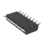 NB2308AI2DG

The activity of extra discounts on wholesale prices is in full swing…
Please fill in your contact information and we will send you the latest wholesale price list.






