 ChipApex | Global Electronic Components Supplier

SEARCH
Search Product
Search Post
— IC芯片 | 连接器 | 传感器 | 被动器件 —
Search productSearch post
— IC芯片 | 连接器 | 传感器 | 被动器件 —
Consult the customer manager about the wholesale price.
consultation hotline:86-132-6715-2157
email:[email protected]
Contact the product manager for consultation. One-stop consultation is available.
Do you want a lower wholesale price? Please send us your inquiry and we will reply immediately.
The NB2308AI4DR2G is a 3.3 V zero delay clock buffer manufactured by onsemi, utilizing advanced 0.35 µm CMOS technology. It features an internal phase-locked loop (PLL) that locks to an input clock presented on the REF pin, with feedback driven from one of the outputs to the FBK pin. This configuration ensures an input-to-output propagation delay of less than 250 ps and output-to-output skew of less than 200 ps. The device provides eight buffered clock outputs divided into two banks of four, supporting frequencies from 15 MHz to 133.3 MHz. It operates within a supply voltage range of 3.0 V to 3.6 V and is available in a 16-pin SOIC package.
Verify the industrial temperature rating (-40°C to +85°C) and the specific DR2G suffix indicating tape and reel packaging for the SOIC-16 variant. Confirm RoHS compliance and lead-free status as indicated by the 'G' suffix. Ensure the design utilizes the correct feedback path to achieve the intended 2X frequency multiplication characteristic of the -4 configuration.
Select this component when a 2X clock multiplier with low skew is required for industrial environments. The NB2308AI4 specifically enables 2X clocks on all outputs regardless of whether feedback is taken from Bank A or Bank B. For applications requiring reference frequency distribution instead, consider the NB2308AI1 series. Ensure load capacitance requirements are met, specifying 15 pF for frequencies above 100 MHz.
The NB2308AI4DR2G belongs to the NB2308A family of 3.3 V zero delay buffers. The 'I' designation indicates an industrial temperature range, while '4' specifies the 2X frequency multiplication configuration. The 'D' suffix denotes the SOIC-16 package, and 'R2G' indicates tape and reel shipping with lead-free construction. Other variants include commercial temperature options and different frequency configurations like the NB2308AC1.
Public confirmed substitute part numbers: None identified in verified documentation.
Zero input-output delay is achieved by ensuring all outputs, including the one driving the FBK pin, are uniformly loaded. Adjustments can be made by varying the capacitive load difference between the FBK pin and the other outputs.
The S1 and S2 inputs control the state of the output banks. Setting both to logic high enables the PLL mode where outputs are driven. Setting them to logic low places all outputs in three-state mode and shuts down the PLL. Setting S2 high and S1 low allows the input clock to bypass the PLL and drive the outputs directly for testing.
The maximum operating frequency is 133.3 MHz.
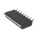 NB2308AI4DR2G

The activity of extra discounts on wholesale prices is in full swing…
Please fill in your contact information and we will send you the latest wholesale price list.






