 ChipApex | Global Electronic Components Supplier

SEARCH
Search Product
Search Post
— IC芯片 | 连接器 | 传感器 | 被动器件 —
Search productSearch post
— IC芯片 | 连接器 | 传感器 | 被动器件 —
Consult the customer manager about the wholesale price.
consultation hotline:86-132-6715-2157
email:[email protected]
Contact the product manager for consultation. One-stop consultation is available.
Do you want a lower wholesale price? Please send us your inquiry and we will reply immediately.
NC7S00M5 is listed in the Inverter Gates range at ChipApex. The manufacturer field lists onsemi. Its product description is IC GATE NAND 1CH 2-INP SOT23-5. Review the specifications below when checking this part for your BOM.
The NC7S00M5X is a single 2-input high-performance CMOS NAND gate from the TinyLogic HS series. It operates within a broad supply voltage range of 2.0 V to 6.0 V and supports an operating temperature range of -40°C to +85°C. The device features balanced propagation delays with typical values of 3.5 ns at 5.0 V (CL=15 pF) and up to 100 ns at 2.0 V (CL=50 pF). Quiescent supply current is less than 1 µA, while output drive capabilities include 2 mA sink and -2 mA source currents. It is housed in a space-saving 5-lead SOT-23 package.
Verify the specific ordering suffix for the required package type. The M5X designation corresponds to the 5-lead SOT-23 package. Confirm RoHS compliance status through official manufacturer documentation prior to integration. Ensure unused inputs are held HIGH or LOW to prevent floating states during operation.
Select this component when a single 2-input NAND function is required in a minimal footprint. The NC7S00M5X is suitable for designs needing balanced propagation delays and robust noise immunity. Consider the 2V to 6V operating range for compatibility with various logic levels. Verify thermal dissipation requirements based on the specific PCB layout and ambient conditions.
This part belongs to the TinyLogic HS family, designed for high-speed performance in small packages. The NC7S00 variant specifically provides a 2-input NAND function. Other members of the series include inverters, NOR gates, and buffers, all sharing similar electrical characteristics and packaging options for system consistency.
NC7S00P5X (SC-70-5 package)
The absolute maximum rating for DC output source or sink current is ±12.5 mA.
Propagation delay increases with higher load capacitance; it is specified as 3.5 ns typ at CL=15 pF and up to 100 ns max at CL=50 pF for 2.0 V operation.
Explore related parts through Logic, Integrated Circuits (ICs), all product categories, ChipApex homepage.
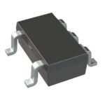 NC7S00M5

The activity of extra discounts on wholesale prices is in full swing…
Please fill in your contact information and we will send you the latest wholesale price list.





