ChipApex | Global Electronic Components Supplier
SEARCH
Search Product
Search Post
— IC芯片 | 连接器 | 传感器 | 被动器件 —
Search productSearch post
— IC芯片 | 连接器 | 传感器 | 被动器件 —
Consult the customer manager about the wholesale price.
consultation hotline:86-132-6715-2157
email:[email protected]
Contact the product manager for consultation. One-stop consultation is available.
Do you want a lower wholesale price? Please send us your inquiry and we will reply immediately.
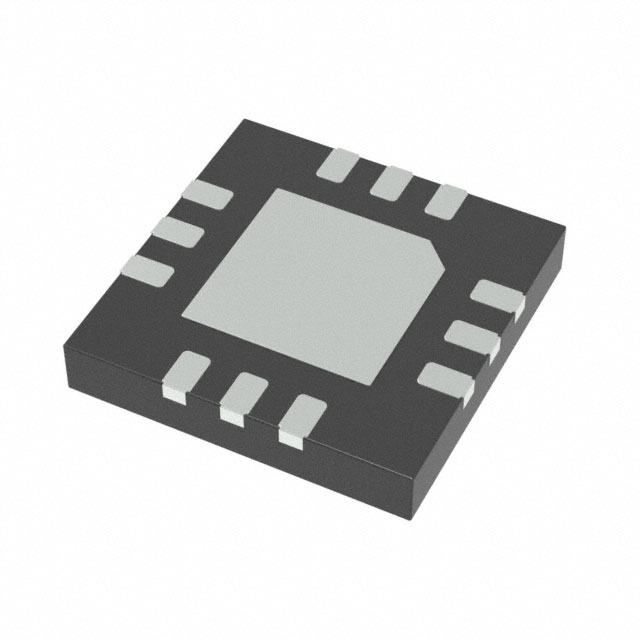
The PAM8904JPR is a piezo sounder driver manufactured by Diodes Incorporated, designed to drive ceramic or piezo sounders with an 18Vpp output from a 5.5V power supply. It features an integrated charge pump boost converter operating at a fixed frequency of 1.0MHz, generating up to a 12V supply. The device supports 1x, 2x, and 3x charge pump modes and can drive loads up to 15nF. It operates within a supply voltage range of 1.8V to 5.5V and includes automatic shutdown and wake-up control for extended battery life. The component is housed in a 12-pin U-QFN3030-12 (Type A) package.
Verify the ordering suffix 'JP' corresponds to the U-QFN3030-12 (Type A) package when sourcing PAM8904JPR. Confirm that the Tape & Reel quantity matches the standard shipping package of 3,000 units per 13-inch carrier. Ensure compliance with RoHS 3 and Halogen-free requirements as specified by the manufacturer.
Select the PAM8904JPR for applications requiring high-efficiency piezo sounder driving with minimal external components. Choose this part if the design necessitates a 12-pin U-QFN3030-12 footprint. Verify that the maximum supply voltage does not exceed 5.5V and that the load capacitance remains within the 15nF limit to ensure proper operation of the integrated charge pump.
The PAM8904 series includes variants such as PAM8904JER (U-QFN3030-16 Type B) and PAM8904GPR (U-QFN2020-12 Type UX). The JPR suffix specifically denotes the 12-pin U-QFN3030-12 package configuration. An automotive-compliant version, PAM8904Q, is available under a separate datasheet for specialized applications.
PAM8904JER serves as a pin-compatible alternative if a 16-pin U-QFN3030-16 package is acceptable. PAM8904GPR is suitable for designs allowing a smaller U-QFN2020-12 footprint. No direct cross-model substitutes are confirmed without verifying package dimensions and pin assignments.
The PAM8904JPR is capable of driving a ceramic/piezo sounder with an 18Vpp output from a 5.5V power supply.
The charge pump mode (1x, 2x, or 3x) is selected using the EN1 and EN2 input pins. The specific logic levels for each mode are defined in the device's truth table.
The device includes thermal shutdown, over-current protection, over-voltage protection, and undervoltage lock-out to ensure reliable operation.
 PAM8904JPR
The activity of extra discounts on wholesale prices is in full swing…
Please fill in your contact information and we will send you the latest wholesale price list.