 ChipApex | Global Electronic Components Supplier
SEARCH
Search Product
Search Post
— IC芯片 | 连接器 | 传感器 | 被动器件 —
Search productSearch post
— IC芯片 | 连接器 | 传感器 | 被动器件 —
Consult the customer manager about the wholesale price.
consultation hotline:86-132-6715-2157
email:[email protected]
Contact the product manager for consultation. One-stop consultation is available.
Do you want a lower wholesale price? Please send us your inquiry and we will reply immediately.
The Nexperia PUMD6,115 is a dual pre-biased NPN/PNP transistor array housed in a compact SOT-363 (SC-88) surface-mount package. It integrates two transistors with built-in base resistors to simplify circuit design and reduce component count. Key electrical specifications include a maximum collector-emitter voltage (VCEO) of 50 V and a continuous collector current (IC) of 100 mA. The device features a minimum DC current gain (hFE) of 30 at specified test conditions and supports a maximum power dissipation (Pd) of 300 mW. It operates within an extended temperature range from -65°C to +150°C, ensuring reliability in demanding environments.
Verify the specific suffix '115' corresponds to the standard tape-and-reel packaging configuration required by your assembly line. Confirm RoHS compliance status through official Nexperia documentation prior to procurement. Ensure that the ordering code matches the exact SOT-363 variant intended for your PCB footprint to avoid mechanical incompatibility during placement.
Select this component when space-constrained designs require dual transistor functionality with integrated biasing. Compare the 180 MHz transition frequency against application speed requirements. Evaluate the 300 mW power dissipation limit against expected thermal loads. Consider the SOT-363 package dimensions relative to available board real estate compared to larger alternatives like SOT-23 arrays.
The PUMD6 belongs to Nexperia's extensive portfolio of pre-biased resistor-equipped transistors (PREMT). These devices are designed to replace discrete transistor-resistor combinations, thereby reducing solder joints and improving assembly yield. The PUMD6 specifically offers a balanced NPN/PNP configuration suitable for push-pull or complementary logic applications within compact mobile and portable electronic devices.
Potential substitutes include the PUMD3,115 and PUMD9,115, which share the same SOT-363 package and similar electrical characteristics. Verify internal resistor values and hFE ranges before substitution to ensure circuit compatibility. Cross-reference datasheets for pinout consistency to prevent installation errors.
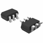 PUMD6,115
The activity of extra discounts on wholesale prices is in full swing…
Please fill in your contact information and we will send you the latest wholesale price list.




