ChipApex | Global Electronic Components Supplier
SEARCH
Search Product
Search Post
— IC芯片 | 连接器 | 传感器 | 被动器件 —
Search productSearch post
— IC芯片 | 连接器 | 传感器 | 被动器件 —
Consult the customer manager about the wholesale price.
consultation hotline:86-132-6715-2157
email:[email protected]
Contact the product manager for consultation. One-stop consultation is available.
Do you want a lower wholesale price? Please send us your inquiry and we will reply immediately.
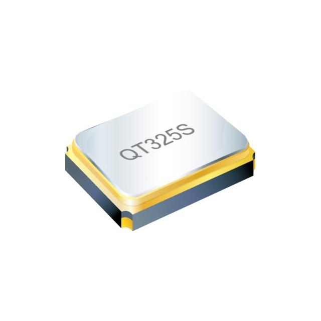
The QT325S-25.000MEDK-T is a quartz crystal resonator manufactured by QST, operating at a fundamental frequency of 25 MHz. It features a load capacitance of 10 pF and an equivalent series resistance (ESR) of 50 Ohms. The component exhibits a frequency tolerance and stability of ±10 ppm within the -20°C to +70°C temperature range. It utilizes a 4-SMD, no lead package with dimensions of 3.2 mm x 2.5 mm x 0.7 mm, designed for surface mount technology applications requiring precise timing signals.
Verify the specific suffix MEDK against official QST documentation to confirm the ±10 ppm stability and -20°C to +70°C operating range. Ensure the 10 pF load capacitance matches the target oscillator circuit design requirements before procurement. Cross-reference the 4-SMD no-lead footprint dimensions with the PCB layout specifications to guarantee proper assembly and soldering integrity during manufacturing.
Select this component when a 25 MHz reference requires ±10 ppm stability within the -20°C to +70°C range. The 10 pF load capacitance and 50 Ohm ESR must align with the host oscillator's electrical characteristics. The 3.2x2.5mm SMD form factor suits space-constrained designs. Confirm that the application environment remains within the specified thermal limits to maintain frequency accuracy throughout the operational lifecycle.
This part belongs to the QT325S series of surface mount crystals from QST. The series offers various frequency and stability options in a standardized 3.2x2.5mm package. The MEDK suffix specifically denotes the ±10 ppm stability grade and temperature range, distinguishing it from other variants like MAHJ or MEEQ which offer different tolerances or load capacitances within the same physical footprint family.
The 7M-25.000METE-T from TXC Corporation is listed as a parametric equivalent substitute. Verify that the replacement maintains the required 10 pF load capacitance and ±10 ppm stability. Ensure the 4-SMD no-lead package dimensions are compatible with the existing PCB footprint before implementing any substitution.
 QT325S-25.000MEDK-T
The activity of extra discounts on wholesale prices is in full swing…
Please fill in your contact information and we will send you the latest wholesale price list.