 ChipApex | Global Electronic Components Supplier
R1224N152M-TR-FE
Search Product
Search Post
— IC芯片 | 连接器 | 传感器 | 被动器件 —
Search productSearch post
— IC芯片 | 连接器 | 传感器 | 被动器件 —
Consult the customer manager about the wholesale price.
consultation hotline:86-132-6715-2157
email:[email protected]
Contact the product manager for consultation. One-stop consultation is available.
Do you want a lower wholesale price? Please send us your inquiry and we will reply immediately.
The R1224N152M-TR-FE is a non-isolated buck DC/DC controller manufactured by Nisshinbo Micro Devices. It supports an input voltage range of 2.3 V to 18.5 V and operates at a switching frequency of 180 kHz. The device features PWM and VFM modes with a maximum duty cycle of 100%. It provides one adjustable output voltage ranging from 1 V to 18.5 V. The controller draws a typical operating supply current of 20 uA and functions within a temperature range of -40°C to +85°C. It is housed in a compact SOT-23-5 package.
Verify the specific suffix 'M' indicates the adjustable output variant distinct from fixed voltage versions within the R1224N series. Confirm that the SOT-23-5 package orientation matches your PCB footprint requirements. Ensure the design accommodates the 180 kHz switching frequency to minimize electromagnetic interference. Validate that the external inductor and capacitor selections comply with the controller's stability criteria for the intended output voltage range.
Select this component when an adjustable output voltage is required rather than a fixed rail. Consider the 180 kHz switching frequency as a balance between component size and noise. Evaluate the 20 uA quiescent current against system sleep power budgets. Compare against other R1224N variants if fixed voltages like 1.8 V or 2.5 V suffice, which may offer simplified design constraints.
This part belongs to the R1224N series of synchronous buck controllers designed for low-power applications. It shares the same core architecture and packaging as other members like the R1224N102M and R1224N252E, differing primarily in output configuration. The series targets mobile and IoT devices where small form factors and high efficiency are critical.
Public confirmed substitute part numbers are not available in the provided documentation. Designers should consult official cross-reference lists or contact the manufacturer for validated alternatives.
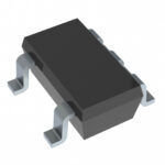 R1224N152M-TR-FE
The activity of extra discounts on wholesale prices is in full swing…
Please fill in your contact information and we will send you the latest wholesale price list.





