ChipApex | Global Electronic Components Supplier
SEARCH
Search Product
Search Post
— IC芯片 | 连接器 | 传感器 | 被动器件 —
Search productSearch post
— IC芯片 | 连接器 | 传感器 | 被动器件 —
Consult the customer manager about the wholesale price.
consultation hotline:86-132-6715-2157
email:[email protected]
Contact the product manager for consultation. One-stop consultation is available.
Do you want a lower wholesale price? Please send us your inquiry and we will reply immediately.
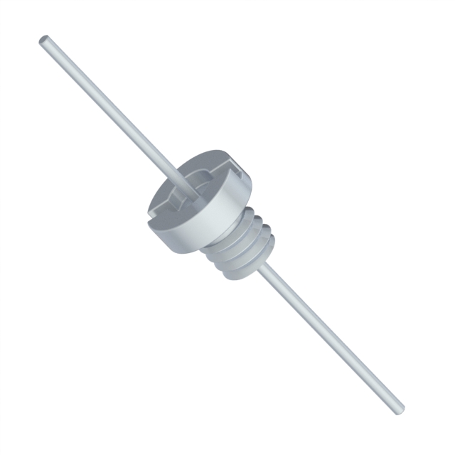
The Knowles Syfer SFJEC2K00471MC1 is an axial feedthrough capacitor with a capacitance of 470 pF and a voltage rating of 2 kV. It features a bushing mounting style and supports a current of 15 A. The component utilizes a ceramic dielectric construction suitable for high-frequency filtering applications.
Verify the specific datasheet revision and RoHS compliance status directly with Knowles Syfer before procurement, as environmental certifications may vary by production batch. Confirm that the axial bushing footprint matches the mechanical constraints of the target enclosure. Ensure that the 15 A current rating and 2 kV breakdown voltage align with the system's operational stress limits to prevent premature failure or insulation breakdown during high-stress transient events.
Select this component when axial feedthrough topology is required for superior EMI shielding compared to surface mount alternatives. The 2 kV rating distinguishes it from lower-voltage MLCCs, making it suitable for high-potential isolation needs. Consider the 15 A current capacity against the load requirements. This part is ideal for applications demanding robust grounding paths through chassis walls where space allows for bushing-style installation rather than standard PCB-mounted capacitors.
The SFJEC series represents Knowles Syfer's specialized line of feedthrough capacitors designed for high-reliability environments. These components integrate the capacitor element directly into the connector or panel mount structure, providing a low-inductance path to ground. This architecture minimizes parasitic effects often associated with traditional discrete capacitor installations, ensuring effective high-frequency noise attenuation in sensitive RF and power electronics.
No direct public substitute part numbers are confirmed for this specific axial feedthrough model. Alternative solutions may require redesigning the mechanical interface to accommodate different form factors such as SMD or radial leaded variants, which would alter the grounding strategy and PCB layout requirements.
 SFJEC2K00471MC1
The activity of extra discounts on wholesale prices is in full swing…
Please fill in your contact information and we will send you the latest wholesale price list.