 ChipApex | Global Electronic Components Supplier

SEARCH
Search Product
Search Post
— IC芯片 | 连接器 | 传感器 | 被动器件 —
Search productSearch post
— IC芯片 | 连接器 | 传感器 | 被动器件 —
Consult the customer manager about the wholesale price.
consultation hotline:86-132-6715-2157
email:[email protected]
Contact the product manager for consultation. One-stop consultation is available.
Do you want a lower wholesale price? Please send us your inquiry and we will reply immediately.
The SG-9101CA-C02PGCBB is a programmable spread spectrum crystal oscillator (XO) manufactured by Epson. It features a CMOS output and operates within a supply voltage range of 1.62V to 3.63V. The device supports a frequency range from 670 kHz to 170 MHz and includes an enable/disable function for power management. It is housed in a compact 4-SMD, no-lead package with dimensions of 2.50mm x 2.00mm x 0.80mm maximum height. The unit is designed for operation across a temperature range of -40°C to +85°C.
This component is typically supplied as a programmed unit where the specific frequency is determined at the time of order. Buyers must verify that the requested frequency falls within the 670 kHz to 170 MHz operational range. Ensure that the supply voltage requirements align with the system design, as the device operates between 1.62V and 3.63V. Confirm the package type matches the PCB footprint specifications before finalizing procurement.
Select this model when a small form factor programmable oscillator with spread spectrum features is required. The CMOS output interface is suitable for standard digital logic families. Consider the thermal performance within the -40°C to +85°C range for environmental suitability. Verify that the enable/disable pin requirement fits the system's power management strategy. The 4-SMD package necessitates appropriate surface mount assembly capabilities.
The SG-9101CA-C02PGCBB belongs to Epson's SG-9101 series of programmable crystal oscillators. This series is characterized by its small footprint and flexible frequency programming options. The CA suffix indicates specific package and pin configuration details within the broader product line. These oscillators are engineered to provide stable clock signals while minimizing electromagnetic interference through spread spectrum technology.
Direct replacements should be sought from the same SG-9101 series family to ensure compatibility. Verify that any substitute part maintains the same 4-SMD package dimensions and pinout. Check that the replacement supports the required frequency range and voltage levels. Cross-reference the enable/disable functionality and output type to guarantee system integration without modification.
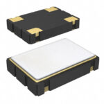 SG-9101CA-C02PGCBB

The activity of extra discounts on wholesale prices is in full swing…
Please fill in your contact information and we will send you the latest wholesale price list.





