 ChipApex | Global Electronic Components Supplier

SEARCH
Search Product
Search Post
— IC芯片 | 连接器 | 传感器 | 被动器件 —
Search productSearch post
— IC芯片 | 连接器 | 传感器 | 被动器件 —
Consult the customer manager about the wholesale price.
consultation hotline:86-132-6715-2157
email:[email protected]
Contact the product manager for consultation. One-stop consultation is available.
Do you want a lower wholesale price? Please send us your inquiry and we will reply immediately.
SN74ACT238PWR is listed in the Signal Switches, Multiplexers, Decoders range at ChipApex. The manufacturer field lists Texas Instruments. Its product description is 4.5V TO 5.5V 3-LINE TO 8-LINE IN. Review the specifications below when checking this part for your BOM.
The SN74ACT238PWR is a high-speed silicon gate CMOS decoder manufactured by Texas Instruments. It implements a 3-to-8 decoding function with non-inverted outputs and TTL-compatible inputs. The device operates within a supply voltage range of 4.5V to 5.5V, featuring balanced push-pull outputs capable of continuous ±24mA drive at 5V. Propagation delays are specified with a maximum of 10.9ns from address inputs to outputs. It includes three strobe inputs (G2, G1, G0) for cascading and demultiplexing control.
Verify the specific package variant, as the SN74ACT238 family includes both TSSOP and WQFN options. Confirm that the ordering suffix matches the required reel quantity and lead finish specifications. Ensure the selected part meets the intended operating temperature range and RoHS compliance requirements for your manufacturing process.
Select this component when a single-channel 3-to-8 decoder with non-inverted outputs is required. It is suitable for systems needing TTL-compatible input thresholds while maintaining CMOS performance characteristics. Consider the thermal pad connectivity if using the WQFN package, or verify trace length constraints for the TSSOP package to maintain signal integrity.
This device belongs to the SN74ACT series of logic integrated circuits. It provides a specialized decoding function distinct from standard gates or flip-flops within the same product line. The ACT series combines the speed of AC logic with the noise immunity and power consumption characteristics of advanced CMOS technology.
SN74ACT238PW
When any of the three strobe inputs (G2, G1, or G0) is inactive, all outputs are forced into the low state. Only when all strobes are active does the decoder enable the selected output based on the address inputs.
Unused TTL-compatible CMOS inputs must not be left floating. They should be terminated to either VCC or ground, typically using a pull-up or pull-down resistor, to prevent oscillations and excessive power consumption.
Explore related parts through Logic, Integrated Circuits (ICs), all product categories, ChipApex homepage.
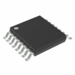 SN74ACT238PWR

The activity of extra discounts on wholesale prices is in full swing…
Please fill in your contact information and we will send you the latest wholesale price list.






