 ChipApex | Global Electronic Components Supplier

SEARCH
Search Product
Search Post
— IC芯片 | 连接器 | 传感器 | 被动器件 —
Search productSearch post
— IC芯片 | 连接器 | 传感器 | 被动器件 —
Consult the customer manager about the wholesale price.
consultation hotline:86-132-6715-2157
email:[email protected]
Contact the product manager for consultation. One-stop consultation is available.
Do you want a lower wholesale price? Please send us your inquiry and we will reply immediately.
SN74ACT7807-40FN is listed in the FIFOs Memory range at ChipApex. The manufacturer field lists Texas Instruments. Its product description is IC FIFO SYNC 2KX9 25NS 44PLCC. Review the specifications below when checking this part for your BOM.
The SN74ACT7807-40FN is a 2048-word by 9-bit clocked first-in, first-out memory device manufactured using low-power advanced CMOS technology. It supports data rates up to 67 MHz with fast access times of 12 ns under a 50-pF load. The component features independent write and read clocks that can be asynchronous or coincident, along with programmable almost-full/almost-empty flags. It operates within a supply voltage range of 4.5 V to 5.5 V and an ambient temperature range of 0°C to 70°C.
Verify the specific suffix -40FN corresponds to the required speed grade and plastic leaded chip carrier package. Confirm the operating temperature range meets application requirements. Ensure power supply decoupling aligns with recommended conditions. Check for latest revision updates on the datasheet before finalizing design specifications.
Select this component when a 2048 x 9 bit FIFO with independent clocking is required. Consider the 12 ns access time and 67 MHz maximum frequency for high-speed parallel interfaces. Evaluate the need for programmable flag offsets if custom buffer thresholds are necessary. Verify compatibility with 5 V logic levels and low-power CMOS requirements.
This device belongs to the SN74ACT series of advanced CMOS logic components. It provides a specialized memory function distinct from standard logic gates. The FN package designation indicates a 44-pin plastic leaded chip carrier format. It is designed for applications requiring reliable data storage and retrieval with precise control over read and write operations.
Public confirmed substitute part numbers are not available in the provided documentation. Verify pinout and electrical characteristics against any potential alternative sources before substitution.
The offset values are programmed after reset and before the first word is written. The Program Enable (PEN) pin must be held low while WRTCLK is high to latch the binary value from D0-D8 and WRTEN1/DP9 as the offset limits.
Resetting requires asserting the RESET input low while at least four transitions of both WRTCLK and RDCLK occur. This clears synchronizing registers and initializes the status flags appropriately.
Explore related parts through Logic, Integrated Circuits (ICs), all product categories, ChipApex homepage.
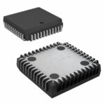 SN74ACT7807-40FN

The activity of extra discounts on wholesale prices is in full swing…
Please fill in your contact information and we will send you the latest wholesale price list.





