 ChipApex | Global Electronic Components Supplier

SEARCH
Search Product
Search Post
— IC芯片 | 连接器 | 传感器 | 被动器件 —
Search productSearch post
— IC芯片 | 连接器 | 传感器 | 被动器件 —
Consult the customer manager about the wholesale price.
consultation hotline:86-132-6715-2157
email:[email protected]
Contact the product manager for consultation. One-stop consultation is available.
Do you want a lower wholesale price? Please send us your inquiry and we will reply immediately.
SN74AHC165QPWRQ1 is listed in the Shift Registers range at ChipApex. The manufacturer field lists Texas Instruments. Its product description is SN74AHC165QPWRQ1. Review the specifications below when checking this part for your BOM.
The SN74AHC165QPWRQ1 is an automotive-grade, 8-bit parallel-load shift register from Texas Instruments. It features a serial-in, parallel-out architecture with separate clocks for the shift and storage registers. The device operates within a supply voltage range of 2 V to 5.5 V and supports an operating temperature range of -40°C to +125°C. It includes a direct overriding clear input, a serial data input for cascading, and 3-state outputs. The component meets AEC-Q100 Grade 1 qualification standards.
Verify the specific package variant (TSSOP or WQFN) required for the design, as the Q1 suffix denotes automotive qualification but does not specify the physical footprint. Confirm that the wettable flank feature is necessary for automated optical inspection requirements if using the QFN package. Ensure the system controller timing aligns with the setup and hold time specifications provided in the datasheet.
Select this component when an 8-bit parallel-to-serial conversion is needed in automotive environments. It is suitable for reducing system controller I/O pins by cascading multiple units. Consider the 2-V to 5.5-V operating range for compatibility with various logic levels. Verify that the output capacitive load does not exceed recommended limits to maintain signal integrity and switching performance.
This part belongs to the SN74AHC165-Q1 family of automotive 8-bit shift registers. It shares functional similarities with other AHC series devices but is specifically qualified for automotive use under AEC-Q100 standards. The 'PWR' suffix indicates a TSSOP-16 package, while the 'Q1' suffix confirms automotive grade. It serves as a digital interface component for expanding input capabilities in vehicle electronics.
SN74AHC165PW
There is no default state for each latch at start-up; the state is unknown until data is loaded or shifted.
Unused inputs must not be left floating. They should be terminated to VCC or GND, typically using a pull-up or pull-down resistor.
Explore related parts through Logic, Integrated Circuits (ICs), all product categories, ChipApex homepage.
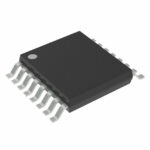 SN74AHC165QPWRQ1

The activity of extra discounts on wholesale prices is in full swing…
Please fill in your contact information and we will send you the latest wholesale price list.





