 ChipApex | Global Electronic Components Supplier

SEARCH
Search Product
Search Post
— IC芯片 | 连接器 | 传感器 | 被动器件 —
Search productSearch post
— IC芯片 | 连接器 | 传感器 | 被动器件 —
Consult the customer manager about the wholesale price.
consultation hotline:86-132-6715-2157
email:[email protected]
Contact the product manager for consultation. One-stop consultation is available.
Do you want a lower wholesale price? Please send us your inquiry and we will reply immediately.
SN74AHC257QPWRQ1 is listed in the Signal Switches, Multiplexers, Decoders range at ChipApex. The manufacturer field lists Texas Instruments. Its product description is AUTOMOTIVE QUADRUPLE 2-INPUT MUL. Review the specifications below when checking this part for your BOM.
The SN74AHC257QPWRQ1 is an automotive-grade quad 2-input data selector/multiplexer with three-state non-inverting outputs. It operates within a supply voltage range of 2V to 5.5V and supports junction temperatures from -40°C to +125°C. The device features low propagation delay, with a maximum of 9.5ns at VCC = 5V and CL = 50pF. Latch-up performance exceeds 250mA per JESD 17 standards. It is available in TSSOP-16 (PW) and WQFN-16 (BQB) packages.
Verify the specific package suffix corresponds to the required form factor, as the Q1 series includes both PW (TSSOP) and BQB (WQFN) options. Confirm that the wettable flank feature is present if automatic optical inspection reliability is a design requirement. Ensure the ordering part number matches the exact temperature grade and ESD classification specified for the target automotive environment.
Select this component when designing automotive digital systems requiring high-speed data routing with minimal latency. The wide operating voltage range accommodates various power supply architectures. Consider the thermal resistance metrics provided in the datasheet for PCB layout planning. Verify input transition rates to prevent oscillation and excessive power consumption during switching events.
This device belongs to the Texas Instruments SN74AHC257-Q1 family of automotive quadruple 2-input data selectors. It utilizes balanced CMOS technology to provide symmetric drive capabilities for sourcing and sinking current. The architecture is designed to replace standard logic components in environments demanding higher reliability and extended temperature tolerance.
SN74AHC257PW
Unused standard CMOS inputs must not be left floating. They should be terminated to either VCC or ground using a pull-up or pull-down resistor, typically 10kΩ, to ensure valid logic states.
The OE (Output Enable) pin controls all outputs simultaneously. When high, the outputs enter a high-impedance state; when low, they assume the logic state determined by the A/B select input.
Explore related parts through Logic, Integrated Circuits (ICs), all product categories, ChipApex homepage.
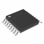 SN74AHC257QPWRQ1

The activity of extra discounts on wholesale prices is in full swing…
Please fill in your contact information and we will send you the latest wholesale price list.





