 ChipApex | Global Electronic Components Supplier

SEARCH
Search Product
Search Post
— IC芯片 | 连接器 | 传感器 | 被动器件 —
Search productSearch post
— IC芯片 | 连接器 | 传感器 | 被动器件 —
Consult the customer manager about the wholesale price.
consultation hotline:86-132-6715-2157
email:[email protected]
Contact the product manager for consultation. One-stop consultation is available.
Do you want a lower wholesale price? Please send us your inquiry and we will reply immediately.
SN74AHC594QPWRQ1 is listed in the Shift Registers range at ChipApex. The manufacturer field lists Texas Instruments. Its product description is AUTOMOTIVE 2V-TO-5.5V 8-BIT SHIF. Review the specifications below when checking this part for your BOM.
The SN74AHC594-Q1 is an automotive-grade, 8-bit serial-in, parallel-out shift register with an output storage register. It operates within a supply voltage range of 2V to 5.5V and supports temperatures from -40°C to +125°C. The device features separate positive-edge triggered clocks for the shift (SRCLK) and storage (RCLK) registers, along with active-low asynchronous clear inputs (SRCLR, RCLR). It includes a serial output (QH') for cascading and balanced CMOS push-pull outputs.
Verify that the specific ordering suffix matches the required package type, as the SN74AHC594-Q1 family includes both TSSOP and WQFN variants. Confirm the component meets AEC-Q100 Grade 1 requirements for your target operating temperature range. Ensure input signals transition quickly to prevent oscillation due to standard CMOS input characteristics.
Select this component when an automotive-qualified shift register with separate storage control is needed. It is suitable for designs requiring simple GPIO control without complex communication interfaces. Consider the wettable flank option if automated optical inspection reliability is a priority. Verify that the load capacitance does not exceed recommended limits to maintain switching performance.
This part belongs to the Texas Instruments SN74AHC594-Q1 family of automotive logic devices. It is designed to replace standard shift registers in automotive environments where extended temperature ranges and high reliability are mandatory. The device integrates latching logic circuitry to maintain volatile memory states during operation.
SN74AHC594PWQ1
At power-up, the state of each latch is unknown because there is no default state defined for the latching logic circuits upon start-up.
Unused inputs must never be left floating. They should be terminated directly to VCC or GND, or connected via a pull-up/pull-down resistor to ensure valid input voltages.
Explore related parts through Logic, Integrated Circuits (ICs), all product categories, ChipApex homepage.
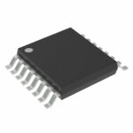 SN74AHC594QPWRQ1

The activity of extra discounts on wholesale prices is in full swing…
Please fill in your contact information and we will send you the latest wholesale price list.






