 ChipApex | Global Electronic Components Supplier

SEARCH
Search Product
Search Post
— IC芯片 | 连接器 | 传感器 | 被动器件 —
Search productSearch post
— IC芯片 | 连接器 | 传感器 | 被动器件 —
Consult the customer manager about the wholesale price.
consultation hotline:86-132-6715-2157
email:[email protected]
Contact the product manager for consultation. One-stop consultation is available.
Do you want a lower wholesale price? Please send us your inquiry and we will reply immediately.
SN74AHCT138N is listed in the Signal Switches, Multiplexers, Decoders range at ChipApex. The manufacturer field lists Texas Instruments. Its product description is IC DECODER/DEMUX 1X3:8 16DIP. Review the specifications below when checking this part for your BOM.
The SN74AHCT138N is a 3-line to 8-line decoder/demultiplexer from the Texas Instruments AHCT logic family, housed in a 16-pin PDIP package. It operates within a supply voltage range of 1.5 V to 5.5 V and supports an operating temperature range of -40°C to +85°C. The device features TTL-compatible inputs and provides three enable inputs (one active-high G1, two active-low G2A/G2B) for simplified cascading. Electrical characteristics include a maximum propagation delay of 12 ns at 5 V with 15 pF load, and output drive capabilities of ±8 mA.
Verify the specific ordering suffix 'N' corresponds to the PDIP-16 package configuration. Confirm RoHS compliance status and lead finish details via the latest Package Option Addendum. Ensure the procurement channel sources production-active parts, as some alternative packages may be obsolete.
Select this component when TTL input compatibility is required alongside CMOS low power consumption. The AHCT series bridges the gap between older TTL standards and modern CMOS processes. Consider the PDIP package only if through-hole mounting is strictly necessary for the mechanical design constraints.
This part belongs to the SNx4AHCT138 family, which includes variants in SOIC, SSOP, TSSOP, and VQFN packages. The 'SN74' prefix denotes commercial grade temperature ratings, while 'AHCT' specifies the high-speed CMOS technology with TTL-compatible inputs. Other family members share identical logical functionality but differ in physical footprint and thermal characteristics.
Direct pin-compatible substitutes include SN74AHCT138DR (SOIC), SN74AHCT138PWR (TSSOP), and SN74AHCT138DBR (SSOP). Verify that the replacement package meets the board's mechanical and thermal requirements.
The device requires G1 to be High and both G2A and G2B to be Low for any output to be active. If these conditions are not met, all outputs remain High.
All unused inputs must be connected to either VCC or GND to prevent undefined operational states caused by floating voltages.
Explore related parts through Logic, Integrated Circuits (ICs), all product categories, ChipApex homepage.
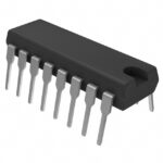 SN74AHCT138N

The activity of extra discounts on wholesale prices is in full swing…
Please fill in your contact information and we will send you the latest wholesale price list.






