 ChipApex | Global Electronic Components Supplier
SEARCH
Search Product
Search Post
— IC芯片 | 连接器 | 传感器 | 被动器件 —
Search productSearch post
— IC芯片 | 连接器 | 传感器 | 被动器件 —
Consult the customer manager about the wholesale price.
consultation hotline:86-132-6715-2157
email:[email protected]
Contact the product manager for consultation. One-stop consultation is available.
Do you want a lower wholesale price? Please send us your inquiry and we will reply immediately.
The SN74AHCT373DBRG4 is an octal transparent D-type latch with 3-state outputs manufactured by Texas Instruments. It operates within a supply voltage range of 4.5V to 5.5V and features TTL-compatible inputs. The device provides balanced CMOS 3-state outputs capable of sourcing and sinking up to 8mA. Propagation delay is specified at 9.5ns maximum at 5V VCC with a load capacitance of 15pF. It is housed in a 20-pin SSOP package.
Verify the specific ordering suffix 'G4' corresponds to lead-free manufacturing and RoHS compliance as indicated by manufacturer documentation. Confirm the DB package designation matches the required 20-pin SSOP footprint for your PCB layout. Ensure the component meets the recommended operating conditions for your target application environment.
Select this component when an octal latch with 3-state capability is required for systems operating strictly at 5V logic levels. The AHCT series ensures compatibility with TTL input thresholds while maintaining CMOS performance characteristics. Consider the SSOP package dimensions and thermal properties during the design phase to ensure proper board integration.
This part belongs to the SNx4AHCT373 family of octal transparent D-type latches. The 'SN74' prefix indicates commercial temperature range operation, while 'AHCT' specifies the advanced high-speed CMOS technology with TTL-compatible inputs. The 'DB' suffix identifies the 20-pin shrink small-outline package variant.
Direct replacements include other SN74AHCT373 variants from Texas Instruments with different package options such as TSSOP (PW), SOIC (DW), or VQFN (RKS). Cross-manufacturer equivalents may exist but require verification of pinout compatibility and electrical specifications against the official datasheet.
The OE (Output Enable) pin controls the state of the outputs. When OE is low, the outputs are actively driven. When OE is high, the outputs enter a high-impedance state, disconnecting them from the circuit.
Unused inputs must not be left floating. They should be terminated to either VCC or ground to prevent excessive power consumption and potential oscillations caused by slow input transitions.
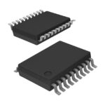 SN74AHCT373DBRG4
The activity of extra discounts on wholesale prices is in full swing…
Please fill in your contact information and we will send you the latest wholesale price list.






