 ChipApex | Global Electronic Components Supplier
SEARCH
Search Product
Search Post
— IC芯片 | 连接器 | 传感器 | 被动器件 —
Search productSearch post
— IC芯片 | 连接器 | 传感器 | 被动器件 —
Consult the customer manager about the wholesale price.
consultation hotline:86-132-6715-2157
email:[email protected]
Contact the product manager for consultation. One-stop consultation is available.
Do you want a lower wholesale price? Please send us your inquiry and we will reply immediately.
The SN74AHCT573NSRE4 is an octal transparent D-type latch with 3-state outputs manufactured by Texas Instruments. It operates within a supply voltage range of 4.5 V to 5.5 V and supports an operating temperature range from -40°C to +85°C. The device features TTL-voltage compatible inputs, high-impedance output states controlled by a buffered OE input, and ESD protection exceeding JESD 22 standards. Propagation delays are specified at 6.5 ns (max) for D-to-Q transitions and 10 ns (max) for OE-to-Q transitions under standard load conditions.
Verify the specific ordering suffix 'R' indicates tape and reel packaging configuration. Confirm that the 'E4' suffix denotes lead-free material composition and RoHS compliance status. Ensure the NS package designation matches the required SOIC-20 footprint for PCB layout compatibility. Cross-reference the manufacturer's latest datasheet revision to confirm current production status and parameter validity.
Select this component when TTL-compatible logic levels are required alongside CMOS performance characteristics. The AHCT series provides faster switching speeds compared to standard HC devices while maintaining electrical compatibility with TTL inputs. Consider the 3-state output capability if the design requires shared bus lines or multiplexed data paths where high-impedance isolation is necessary.
This part belongs to the SN74AHCT573 family of octal transparent D-type latches. The family includes variants with different package types such as DIP, SOIC, TSSOP, and SSOP. All members share identical internal logic functionality but differ in physical dimensions, thermal characteristics, and manufacturing packaging formats suitable for various surface-mount and through-hole assembly processes.
SN74AHCT573DWRE4: Same logic function and specifications in SOIC-20 tube packaging instead of tape and reel.
The OE input controls only the external output drivers. It places outputs in a high-impedance state without affecting the internal latching mechanism, allowing new data to be entered or old data retained while outputs are disabled.
Tying OE to VCC via a pullup resistor ensures the outputs default to a high-impedance state during power-up or power-down events, preventing unintended bus driving before the device reaches stable operating conditions.
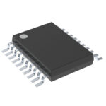 SN74AHCT573NSRE4
The activity of extra discounts on wholesale prices is in full swing…
Please fill in your contact information and we will send you the latest wholesale price list.





