 ChipApex | Global Electronic Components Supplier

SEARCH
Search Product
Search Post
— IC芯片 | 连接器 | 传感器 | 被动器件 —
Search productSearch post
— IC芯片 | 连接器 | 传感器 | 被动器件 —
Consult the customer manager about the wholesale price.
consultation hotline:86-132-6715-2157
email:[email protected]
Contact the product manager for consultation. One-stop consultation is available.
Do you want a lower wholesale price? Please send us your inquiry and we will reply immediately.
The SN74AS257N is a quad 2-to-1 data selector/multiplexer from the Texas Instruments AS logic series, housed in a 16-pin PDIP package. It features four independent channels with shared A/B select and OE (output enable) inputs. The device operates within a supply voltage range of 4.5 V to 5.5 V and supports an operating temperature range of 0°C to 70°C. Electrical characteristics include a maximum propagation delay of 12 ns from input to output and 22 ns for enable/disable transitions under standard load conditions. Outputs are three-state, providing high-level output current of -15 mA and low-level output current of 48 mA.
Verify the specific ordering suffix 'N' corresponds to the plastic DIP-16 package configuration required for your design. Confirm RoHS compliance status as indicated in the manufacturer's packaging addendum. Ensure the procurement channel provides valid traceability documentation consistent with Texas Instruments standards for this component series.
Select the SN74AS257N when AS logic speed is required alongside standard TTL-compatible input levels. This component is suitable for designs needing fast switching speeds with robust drive currents. Consider alternative packages such as SOIC or ceramic DIP if surface mount or military-grade temperature ranges are necessary instead of the standard plastic through-hole option.
This component belongs to the SN74AS25x family of high-speed silicon-gate CMOS logic devices. It shares functional similarities with the SN74ALS257A but offers faster switching characteristics. The device is part of Texas Instruments' legacy 74-series logic portfolio, designed for compatibility with existing TTL-based system architectures while providing improved performance metrics.
Public confirmed substitute part numbers include SN74AS257D (SOIC package variant). Verify pinout and electrical specifications match before substitution.
When the OE input is at a high logic level, all outputs enter a high-impedance state, effectively disconnecting them from the data lines to prevent bus loading.
The A/B input acts as the select line for all four channels simultaneously, determining whether the A or B input data is routed to the respective Y outputs.
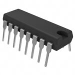 SN74AS257N

The activity of extra discounts on wholesale prices is in full swing…
Please fill in your contact information and we will send you the latest wholesale price list.






