 ChipApex | Global Electronic Components Supplier

SEARCH
Search Product
Search Post
— IC芯片 | 连接器 | 传感器 | 被动器件 —
Search productSearch post
— IC芯片 | 连接器 | 传感器 | 被动器件 —
Consult the customer manager about the wholesale price.
consultation hotline:86-132-6715-2157
email:[email protected]
Contact the product manager for consultation. One-stop consultation is available.
Do you want a lower wholesale price? Please send us your inquiry and we will reply immediately.
SN74LV8T165PWR is listed in the Shift Registers range at ChipApex. The manufacturer field lists Texas Instruments. Its product description is SN74LV8T165PWR. Review the specifications below when checking this part for your BOM.
The SN74LV8T165 is an 8-bit parallel-load shift register from Texas Instruments. It operates on a single supply voltage ranging from 1.65 V to 5.5 V. The device features 5.5-V tolerant inputs and supports both up-translation (e.g., 1.2 V to 1.8 V) and down-translation (e.g., 5.0 V to 3.3 V). It includes latching logic with a known power-up state via a Power On Reset circuit. The package is available in TSSOP-16.
Verify the specific ordering suffix matches the required package type, as variants exist for TSSOP and WQFN. Confirm that the intended operating voltage range aligns with the device's 1.65 V to 5.5 V specification. Ensure input signal transition rates comply with recommended conditions to prevent excessive power consumption or oscillation during operation.
Select this component when a design requires converting parallel inputs to a serial output stream while simultaneously performing voltage level translation. It is suitable for applications needing to interface lower voltage sources with higher voltage logic without external translators. Consider the clock frequency requirements against the specified timing characteristics at the target supply voltage.
This device belongs to the LVxT family of logic ICs designed by Texas Instruments. The family specializes in single-supply voltage translation capabilities, allowing seamless communication between digital components operating at different voltage levels. These devices are commonly used in mixed-voltage embedded systems and industrial control interfaces.
SN74LV8T165PW
The SN74LV8T165 includes a Power On Reset (POR) circuit that sets all internal latching circuits to a known state during the power-up ramp, preventing undefined output states.
No, unused inputs must not be left floating. They should be terminated at VCC or GND, typically using a pull-up or pull-down resistor, to ensure valid logic states and prevent excessive current draw.
Explore related parts through Logic, Integrated Circuits (ICs), all product categories, ChipApex homepage.
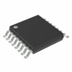 SN74LV8T165PWR

The activity of extra discounts on wholesale prices is in full swing…
Please fill in your contact information and we will send you the latest wholesale price list.





