 ChipApex | Global Electronic Components Supplier

SEARCH
Search Product
Search Post
— IC芯片 | 连接器 | 传感器 | 被动器件 —
Search productSearch post
— IC芯片 | 连接器 | 传感器 | 被动器件 —
Consult the customer manager about the wholesale price.
consultation hotline:86-132-6715-2157
email:[email protected]
Contact the product manager for consultation. One-stop consultation is available.
Do you want a lower wholesale price? Please send us your inquiry and we will reply immediately.
SY10EP11UZI is listed in the Clock Buffers, Drivers range at ChipApex. The manufacturer field lists Microchip Technology. Its product description is IC CLK BUFFER 1:2 3GHZ 8SOIC. Review the specifications below when checking this part for your BOM.
The SY10EP11UZI is a precision, high-speed 1:2 differential fanout buffer from the ECL Pro™ family. It supports PECL, LVPECL, ECL, and LVECL logic families with power supply options of 2.5V, 3.3V, and 5V. The device guarantees AC performance including a maximum toggle frequency (fMAX) exceeding 3.0GHz, within-device skew under 20ps, and propagation delay up to 300ps at VCC = 2.5V. It operates over an industrial temperature range of –40°C to +85°C and is housed in an 8-pin SOIC package.
Verify that the ordering suffix 'Z' corresponds to the 8-pin SOIC package and 'I' indicates the industrial temperature range (-40°C to +85°C). Confirm lead finish specifications if RoHS compliance is required, as standard versions may use Sn-Pb while 'G' suffixes indicate Pb-Free NiPdAu finishes. Ensure power supply decoupling capacitors are placed close to the VCC pin.
Select this component when a 1:2 differential fanout buffer with guaranteed sub-20ps skew is necessary. Compare against the SY100EP11U variant if higher drive current or specific DC electrical characteristics are needed. Ensure the input signal swing falls within the 150mV to 1200mV range for proper operation across all supported voltage levels.
This part belongs to the Micrel ECL Pro™ series, which was acquired by Microchip Technology. The SY10EP11U is designed to replace older devices like the EL11V, offering significantly improved within-device skews and output transition times. It serves as a critical interface component in high-frequency digital circuits requiring low jitter and stable differential signaling.
Cross-reference tables list the MC10EP11D/DT and MC10LVEP11D/DT from ON Semiconductor as equivalent parts. Verify pin compatibility and electrical parameters before substitution.
The differential inputs employ clamping circuitry to maintain stability. If inputs are left floating, the Q outputs will default to LOW.
Single-ended operation is supported on the D pin. For PECL mode, single-ended input CLK pin operation is limited to VCC ≥ 3.0V. In ECL/LVECL modes, it is limited to VEE ≤ –3.0V.
The datasheet recommends Parallel Termination (Thevenin Equivalent) or Three-Resistor Y-Termination. Resistor values vary based on the supply voltage (e.g., R1=130Ω, R2=82Ω for +3.3V).
Explore related parts through Clock/Timing, Integrated Circuits (ICs), all product categories, ChipApex homepage.
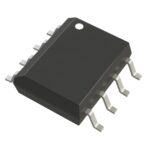 SY10EP11UZI

The activity of extra discounts on wholesale prices is in full swing…
Please fill in your contact information and we will send you the latest wholesale price list.






