 ChipApex | Global Electronic Components Supplier
SEARCH
Search Product
Search Post
— IC芯片 | 连接器 | 传感器 | 被动器件 —
Search productSearch post
— IC芯片 | 连接器 | 传感器 | 被动器件 —
Consult the customer manager about the wholesale price.
consultation hotline:86-132-6715-2157
email:[email protected]
Contact the product manager for consultation. One-stop consultation is available.
Do you want a lower wholesale price? Please send us your inquiry and we will reply immediately.
The TEA6360T/V2,512 is a monolithic 5-band stereo equalizer circuit designed for audio tone processing in automotive and consumer applications. It features two independent channels (Left/Right), each with five filter amplifiers controlled via an I²C bus. The device operates on a supply voltage of 7V to 13.2V with a typical current of 24.5mA. Key electrical parameters include a total signal gain of -0.5dB to 0dB, a frequency response of 0Hz to 20kHz, and crosstalk attenuation exceeding 60dB. It supports variable or constant Q-factor selection and includes a defeat mode for linear bypass.
Verify the package type against the specific suffix: V2 indicates a 32-SOIC (SOT287) surface-mount package. Confirm the reel quantity matches the '512' suffix if applicable to your manufacturing process. Ensure the I²C bus voltage levels are compatible with the host controller, as the device accepts logic levels up to VP.
Select this component when a dedicated hardware-based 5-band graphic equalizer is required for stereo audio paths. It is suitable for designs where external microcontrollers manage tone settings via I²C. Consider the 32-SO package for surface-mount assembly. Ensure the power supply can provide up to 13.2V and handle the peak current requirements during maximum boost operations.
The TEA6360 is part of NXP's (formerly Philips Semiconductors) legacy audio special-purpose integrated circuits. It was originally designed for analog audio processing in vehicle infotainment and home entertainment systems before the widespread adoption of digital signal processors. The 'T' suffix denotes the tape-and-reel packaging variant, while 'V2' specifies the shrink small-outline package.
Direct pin-to-pin replacements may be limited due to the proprietary nature of older Philips/NXP audio ICs. Verify compatibility with existing PCB footprints (SOT287-1). If upgrading to digital solutions, ensure the new DSP can replicate the specific 5-band filter characteristics and I²C control protocol defined in the original design.
The Q-factor can be set to variable or constant modes via I²C commands. Variable Q provides maximum Q at maximum boost/cut, while constant Q maintains a consistent bandwidth across the control range by combining boost and cut steps.
The module address is determined by the state of Pin 18 (MAD). A LOW level on MAD sets the address to 1000 0100, while a HIGH level or open-circuit sets it to 1000 0110.
Setting the defeat bit (DEF=1) bypasses all filters, connecting the input directly to the output amplifier with 0dB gain, resulting in a linear frequency response. The filter settings remain stored but inactive.
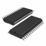 TEA6360T/V2,512
The activity of extra discounts on wholesale prices is in full swing…
Please fill in your contact information and we will send you the latest wholesale price list.





